Asus A7S266-VM/U2 User Manual
Page 26
1-16
Chapter 1: Motherboard Information
7.
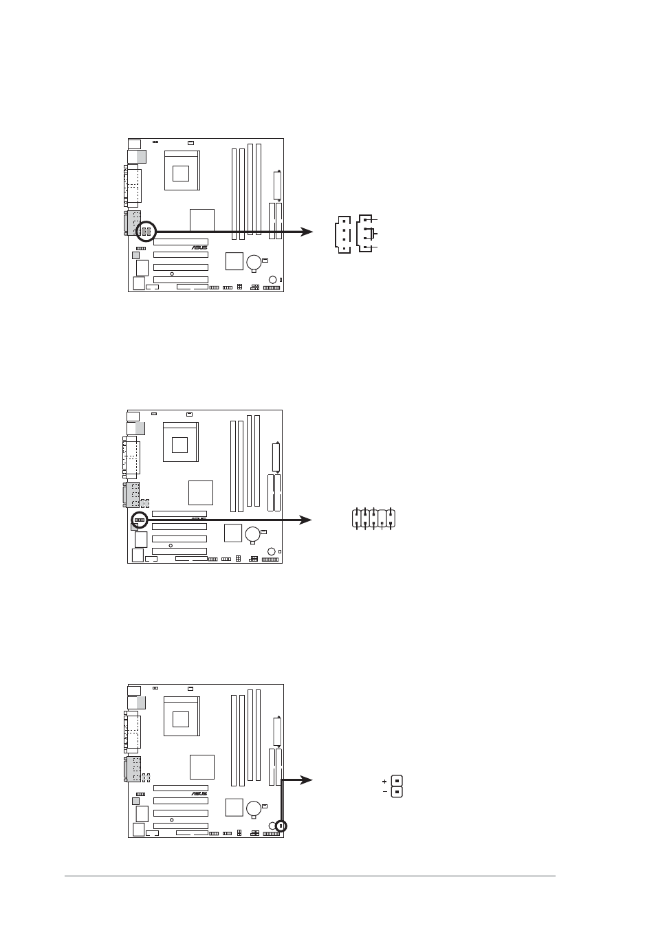
Front panel audio connectors (10-1 pin FP_AUDIO1)
(on audio models only)
This is an interface for the Intel front panel audio cable that allow convenient
connection and control of audio devices.
8.
Hard disk connector (2-pin IDE_LED1)
This 2-pin connector connects to the front panel HD LED and lights up on
every read/write activity of any of the disc drives connected to the primary or
secondary IDE slots.
A7S266-VM/U2
®
A7S266-VM/U2 Audio Panel Connector
FP_AUDIO1
LineOut_RL
MIC
LineOut_FR
LineOut_FL
NC
MICPWR
+5V
A
AGND
LineOut_RR
A7S266-VM/U2
®
A7S266-VM/U2 IDE Activity LED
TIP: If the case-mounted LED does not
light, try reversing the 2-pin plug.
IDE_LED1
6.
Internal audio connectors (4-pin AUX1, CD1) (on audio models only)
These connectors allow you to receive stereo audio input from sound sources
such as a CD-ROM, TV tuner, or MPEG card.
A7S266-VM/U2
®
A7S266-VM/U2 Internal Audio Connectors
AUX1
(White)
CD1
(Black)
Right Audio Channel
Left Audio Channel
Ground
- P5B Premium Vista Edition (188 pages)
- P5B (140 pages)
- P5B (56 pages)
- P5KPL-VM/1394/SI (94 pages)
- M2N68-CM (28 pages)
- P5AD2-E Premium (2 pages)
- P5GD1-VM (88 pages)
- P5AD2 Premium (8 pages)
- P5GD1-VM (92 pages)
- DELUXE A7N8X-E (114 pages)
- P5KPL-AM SE (62 pages)
- P5KPL-AM SE (40 pages)
- P5KPL-AM SE (38 pages)
- P4S8X-X (64 pages)
- P5K-VM (98 pages)
- K8V-X SE (82 pages)
- M2N68-AM SE2 (40 pages)
- P4P800 SE (125 pages)
- P4P800 SE (16 pages)
- DELUXE SERIES M3A32-MVP (176 pages)
- P5AD2 Deluxe (148 pages)
- M4A79 Deluxe (122 pages)
- A7V266-E (108 pages)
- Application Manual (8 pages)
- Application Manual (2 pages)
- Application Manual (6 pages)
- Application Manual (9 pages)
- Application Manual (3 pages)
- Application Manual (1 page)
- Application Manual (5 pages)
- Application Manual (11 pages)
- Application Manual (10 pages)
- Application Manual (4 pages)
- M4A88T-I DELUXE (70 pages)
- M4A88T-I DELUXE (44 pages)
- P9X79 DELUXE (2 pages)
- RAMPAGE IV GENE (1 page)
- P9X79 (156 pages)
- P8H61-M PLUS V3 (64 pages)
- A85XM-A (78 pages)
- M4A78L-M LE (64 pages)
- M2N68-AM (96 pages)
- M2N68-AM (62 pages)
- M2N68-AM (38 pages)
- Blitz Formula (1 page)