Asus A7V333-X User Manual
Page 28
1-18
Chapter 1: Motherboard Information
12.
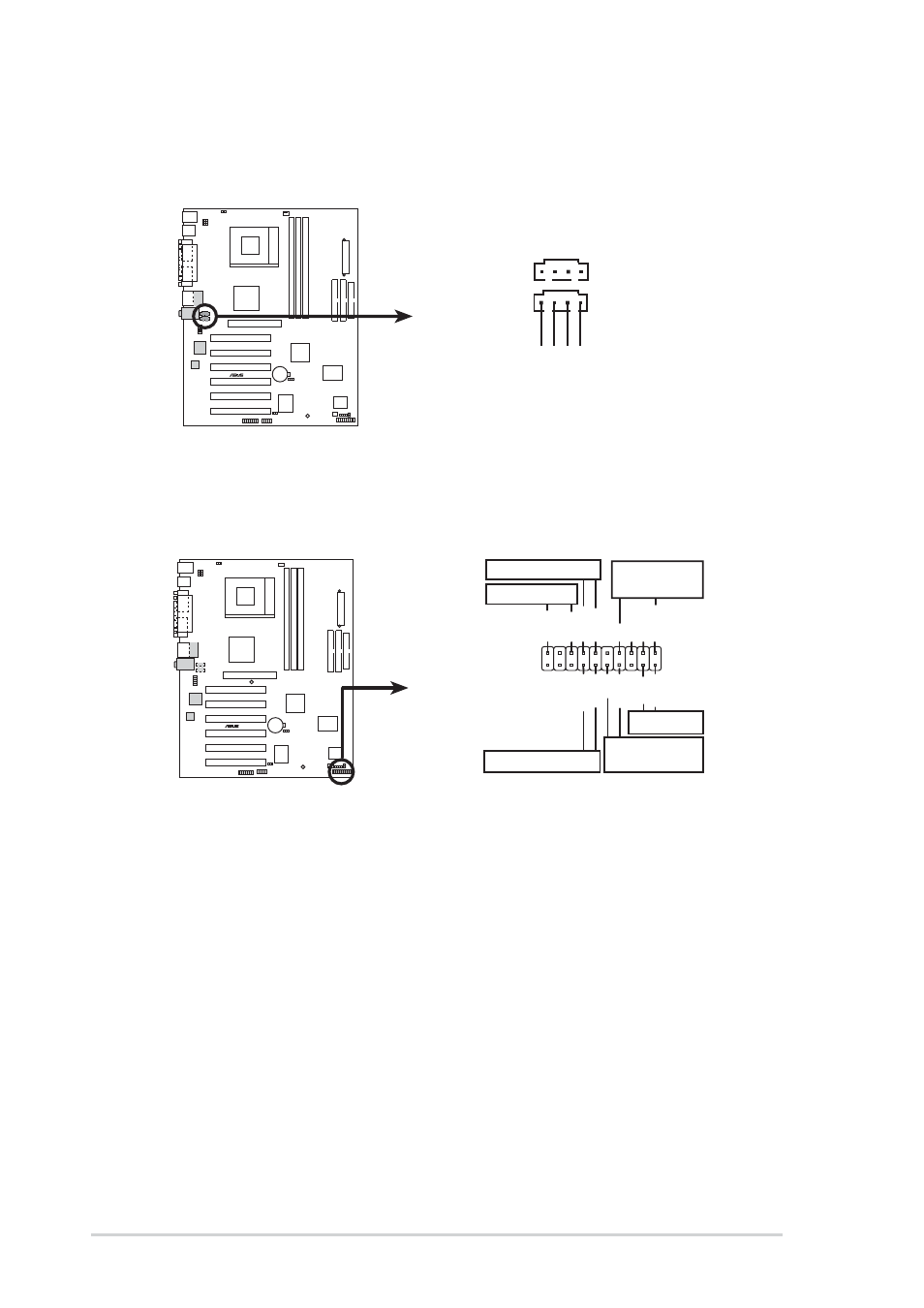
System panel connector (20-pin PANEL1)
This connector accommodates several system front panel functions.
A7V333-X
®
A7V333-X System Panel Connectors
*
Requires an ATX power supply.
PLED-
Ground
PWR
Keylock
+5V
Speaker
Speaker
Connector
Power LED
Ground
Reset SW
SMI Lead
ExtSMI#
Ground
Reset
Ground
Ground
Ground
Keyboard Lock
ATX Power
Switch*
PLED+
11. Internal audio connectors (4-pin CD1, AUX1)(on audio models only)
These connectors allow you to receive stereo audio input from sound
sources such as a CD-ROM, TV tuner, or MPEG card.
A7V333-X
®
A7V333-X Internal Audio Connectors
CD1 (Black)
AUX1 (White)
Right A
udio Channel
Left A
udio Channel
Ground
Ground
•
System Power LED Lead (3-1 pin PLED)
This 3-1 pin connector connects to the system power LED. The LED lights
up when you turn on the system power.
•
Keyboard Lock Lead (2-1 pin KEYLOCK)
This 2-1 pin connector connects to the case-mounted switch to allow the use
of the keyboard lock feature.
•
System Warning Speaker Lead (4-pin SPEAKER)
This 4-pin connector connects to the case-mounted speaker and allows you
to hear system beeps and warnings.