Hardware setup – Asus CUEP2-M User Manual
Page 40
40
ASUS CUEP2-M User’s Manual
Connectors
3. H/W SETUP
3. HARDWARE SETUP
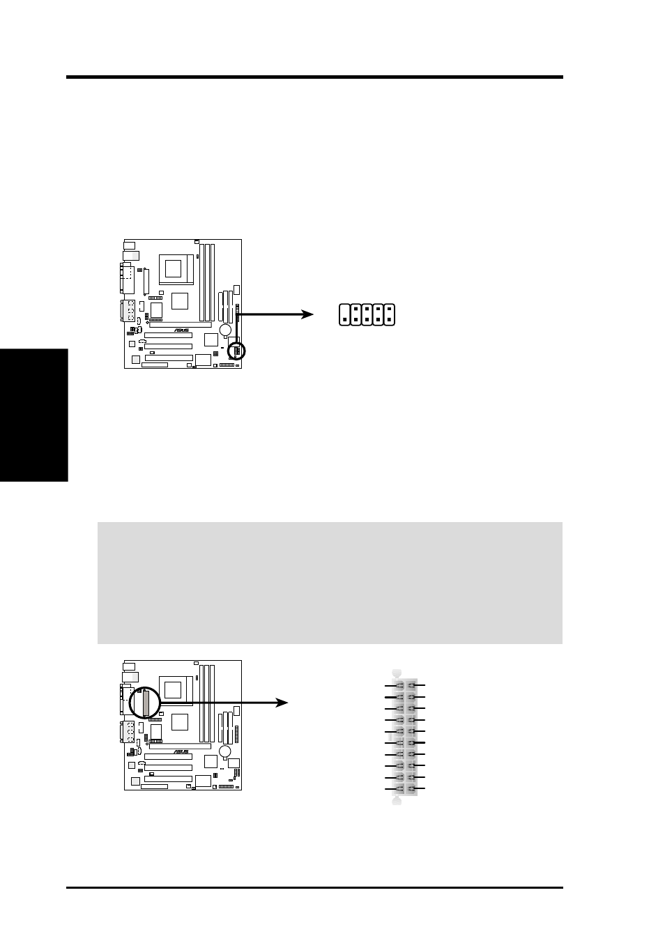
22) USB Headers (10-1 pin USB2)
If the USB Ports on the back panels are inadequate, a USB header is available
for two additional USB ports. Connect the 10-1 pin ribbon cable from the pro-
vided 2-port USB connector set to the midboard 10-1 pin USB header and mount
the USB connector set to an open slot on your chassis.
NOTE: To use this header, make sure that the USBCNR1/USBCNR2 jumpers
(see 3.4 Motherboard Settings) are set to USB Connect.
CUEP2-M USB Headers
USB2
1
5
6
10
1: USB Power
2: USBP2–
3: USBP2+
4: GND
5: NC
6: USB Power
7: USBP3–
8: USBP3+
9: GND
CUEP2-M
®
23) ATX Power Supply Connector (20-pin block ATXPWR)
This connector connects to an ATX power supply. The plug from the power sup-
ply will only insert in one orientation because of the different hole sizes. Find the
proper orientation and push down firmly making sure that the pins are aligned.
IMPORTANT:
Make sure that your ATX power supply (minimum recommended
wattage: 200 watts; 235W for a fully-configured system) can supply at least 20
amperes on the +5-volt lead and at least 10mA (750mA recommended) on the +5-
volt standby lead (+5VSB). Your system may become unstable/unreliable and may
experience difficulty in powering up if your power supply is inadequate. For Wake-
On-LAN support, your ATX power supply must supply at least 750mA +5VSB.
CUEP2-M
®
CUEP2-M ATX Power Connector
+3.3 Volts
-12.0 Volts
Ground
Power Supply On
Ground
Ground
Ground
-5.0 Volts
+5.0 Volts
+5.0 Volts
Power Good
+12.0 Volts
+3.3 Volts
+3.3 Volts
Ground
+5.0 Volts
Ground
+5.0 Volts
Ground
+5V Standby