1 overview overview overview overview overview – Asus A8N-VM CSM/NBP User Manual
Page 20
1 - 1 0
1 - 1 0
1 - 1 0
1 - 1 0
1 - 1 0
C h a p t e r 1 : P r o d u c t i n t r o d u c t i o n
C h a p t e r 1 : P r o d u c t i n t r o d u c t i o n
C h a p t e r 1 : P r o d u c t i n t r o d u c t i o n
C h a p t e r 1 : P r o d u c t i n t r o d u c t i o n
C h a p t e r 1 : P r o d u c t i n t r o d u c t i o n
1.5
System memory
1.5.1
1.5.1
1.5.1
1.5.1
1.5.1
Overview
Overview
Overview
Overview
Overview
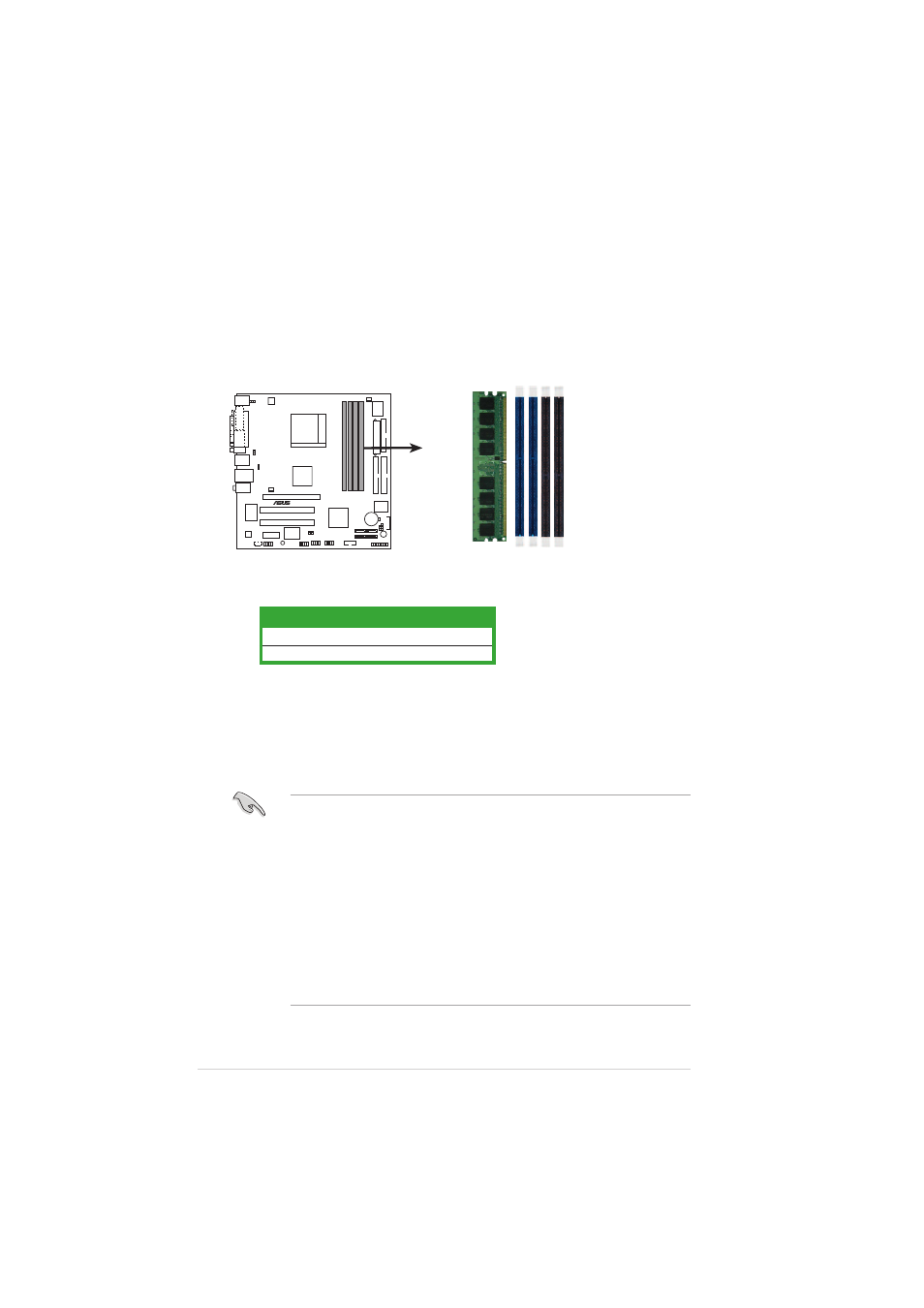
The motherboard comes with four 184-pin Double Data Rate (DDR) Dual
Inline Memory Modules (DIMM) sockets.
The following figure illustrates the location of the sockets:
1.5.2
1.5.2
1.5.2
1.5.2
1.5.2
Memory configurations
Memory configurations
Memory configurations
Memory configurations
Memory configurations
You may install 128 MB, 256 MB, 512 MB, and 1 GB unbuffered non-ECC
DDR DIMMs into the DIMM sockets using the memory configurations in this
section.
•
Installing DDR DIMMs other than the recommended configurations
may cause memory sizing error or system boot failure.
•
Install only identical (the same type and size) DDR DIMM pairs for
each channel.
•
Always install DIMMs with the same CAS latency. For optimum
compatibility, we recommend that you obtain memory modules from
the same vendor.
•
Due to chipset limitation, this motherboard does not support DIMM
modules with less than or equal to 128 Mb memory chips.
•
If you are installing only one DIMM module for a Single-channel
configuration, install the module on DIMM_A1 (blue slot).
C h a n n e l
C h a n n e l
C h a n n e l
C h a n n e l
C h a n n e l
S o c k e t s
S o c k e t s
S o c k e t s
S o c k e t s
S o c k e t s
Channel 1
DIMM_A1 and DIMM_B1
Channel 2
DIMM_A2 and DIMM_B2
A8N-VM
®
A8N-VM 184-pin DDR DIMM sockets
DIMM_A2
DIMM_A1
DIMM_B2
DIMM_B1