3 connectors – Asus TS500-E2 User Manual
Page 89
4 - 9
4 - 9
4 - 9
4 - 9
4 - 9
A S U S T S 5 0 0 - E 2
A S U S T S 5 0 0 - E 2
A S U S T S 5 0 0 - E 2
A S U S T S 5 0 0 - E 2
A S U S T S 5 0 0 - E 2
4.3
Connectors
4.3.1
4.3.1
4.3.1
4.3.1
4.3.1
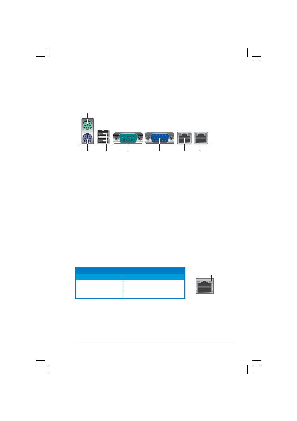
Rear panel connectors
Rear panel connectors
Rear panel connectors
Rear panel connectors
Rear panel connectors
1 .
1 .
1 .
1 .
1 .
P S / 2 m o u s e p o r t ( g r e e n ) .
P S / 2 m o u s e p o r t ( g r e e n ) .
P S / 2 m o u s e p o r t ( g r e e n ) .
P S / 2 m o u s e p o r t ( g r e e n ) .
P S / 2 m o u s e p o r t ( g r e e n ) . This port is for a PS/2 mouse.
2 .
2 .
2 .
2 .
2 .
P S / 2 k e y b o a r d p o r t ( p u r p l e ) .
P S / 2 k e y b o a r d p o r t ( p u r p l e ) .
P S / 2 k e y b o a r d p o r t ( p u r p l e ) .
P S / 2 k e y b o a r d p o r t ( p u r p l e ) .
P S / 2 k e y b o a r d p o r t ( p u r p l e ) . This port is for a PS/2 keyboard.
3 .
3 .
3 .
3 .
3 .
U S B 2 . 0 p o r t s 1 a n d 2 .
U S B 2 . 0 p o r t s 1 a n d 2 .
U S B 2 . 0 p o r t s 1 a n d 2 .
U S B 2 . 0 p o r t s 1 a n d 2 .
U S B 2 . 0 p o r t s 1 a n d 2 . These two 4-pin Universal Serial Bus (USB)
ports are available for connecting USB 2.0 devices.
4 .
4 .
4 .
4 .
4 .
S e r i a l ( C O M 1 ) p o r t
S e r i a l ( C O M 1 ) p o r t
S e r i a l ( C O M 1 ) p o r t
S e r i a l ( C O M 1 ) p o r t
S e r i a l ( C O M 1 ) p o r t. This 9-pin communication port is for pointing
devices or other serial devices.
5 .
5 .
5 .
5 .
5 .
V G A p o r t .
V G A p o r t .
V G A p o r t .
V G A p o r t .
V G A p o r t . This port is for a VGA monitor or other VGA-compatible
devices.
6 .
6 .
6 .
6 .
6 .
G i g a b i t L A N 1 ( R J - 4 5 ) p o r t .
G i g a b i t L A N 1 ( R J - 4 5 ) p o r t .
G i g a b i t L A N 1 ( R J - 4 5 ) p o r t .
G i g a b i t L A N 1 ( R J - 4 5 ) p o r t .
G i g a b i t L A N 1 ( R J - 4 5 ) p o r t . This ports allow Gigabit connection to
a Local Area Network (LAN) through a network hub. Refer to the table
below for the LAN port LED indications.
7 .
7 .
7 .
7 .
7 .
G i g a b i t L A N 2 ( R J - 4 5 ) p o r t .
G i g a b i t L A N 2 ( R J - 4 5 ) p o r t .
G i g a b i t L A N 2 ( R J - 4 5 ) p o r t .
G i g a b i t L A N 2 ( R J - 4 5 ) p o r t .
G i g a b i t L A N 2 ( R J - 4 5 ) p o r t . This ports allow Gigabit connection to
a Local Area Network (LAN) through a network hub. Refer to the table
below for the LAN port LED indications.
LAN port LED indications
LAN port LED indications
LAN port LED indications
LAN port LED indications
LAN port LED indications
A C T / L I N K L E D
A C T / L I N K L E D
A C T / L I N K L E D
A C T / L I N K L E D
A C T / L I N K L E D
S P E E D L E D
S P E E D L E D
S P E E D L E D
S P E E D L E D
S P E E D L E D
S t a t u s
S t a t u s
S t a t u s
S t a t u s
S t a t u s
D e s c r i p t i o n
D e s c r i p t i o n
D e s c r i p t i o n
D e s c r i p t i o n
D e s c r i p t i o n
S t a t u s
S t a t u s
S t a t u s
S t a t u s
S t a t u s
D e s c r i p t i o n
D e s c r i p t i o n
D e s c r i p t i o n
D e s c r i p t i o n
D e s c r i p t i o n
OFF
No link
OFF
10 Mbps connection
GREEN
Linked
ORANGE
100 Mbps connection
BLINKING Data activity
GREEN
1000 Mbps connection
L A N p o r t
L A N p o r t
L A N p o r t
L A N p o r t
L A N p o r t
S P E E D
S P E E D
S P E E D
S P E E D
S P E E D
L E D
L E D
L E D
L E D
L E D
ACT/LINK
ACT/LINK
ACT/LINK
ACT/LINK
ACT/LINK
L E D
L E D
L E D
L E D
L E D
1
2
5
4
6
7
3