Hardware setup, 2 internal connectors, 34 asus tuv4x user’s manual – Asus TUV4X User Manual
Page 34: Connectors 3. h/w setup
34
ASUS TUV4X User’s Manual
3. HARDWARE SETUP
Connectors
3. H/W SETUP
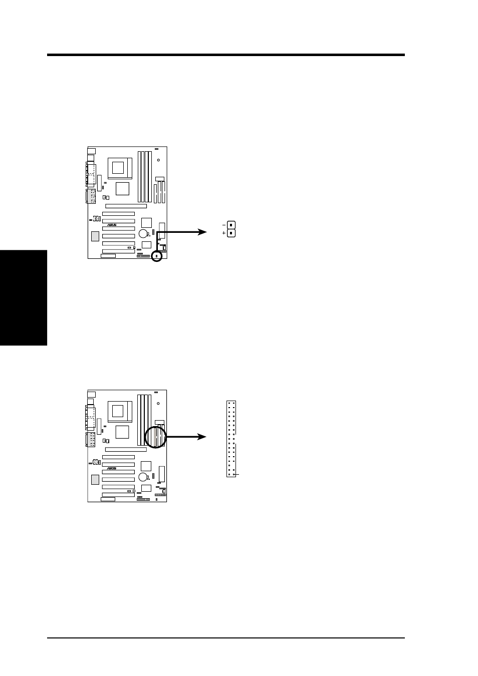
3.8.2 Internal Connectors
1) IDE Activity LED (2-pin IDELED)
This connector supplies power to the cabinet’s IDE activity LED. Read and
write activity by devices connected to the Primary or Secondary IDE connectors
cause the IDE LED to light up.
2) Floppy Disk Drive Connector (34-1 pin FLOPPY)
This connector supports the provided floppy drive ribbon cable. After connecting
the single end to the board, connect the two plugs on the other end to the floppy
drives. (Pin 5 is removed to prevent inserting in the wrong orientation when
using ribbon cables with pin 5 plugged).
TUV4X
®
TUV4X IDE Activity LED
TIP: If the case-mounted LED does not
light, try reversing the 2-pin plug.
IDELED
TUV4X
®
NOTE: Orient the red markings on
the floppy ribbon cable to
PIN 1
TUV4X Floppy Disk Drive Connector
PIN 1
- P5B Premium Vista Edition (188 pages)
- P5B (140 pages)
- P5B (56 pages)
- P5KPL-VM/1394/SI (94 pages)
- M2N68-CM (28 pages)
- P5GD1-VM (92 pages)
- P5AD2-E Premium (2 pages)
- P5GD1-VM (88 pages)
- P5AD2 Premium (8 pages)
- DELUXE A7N8X-E (114 pages)
- P5KPL-AM SE (38 pages)
- P5KPL-AM SE (62 pages)
- P5KPL-AM SE (40 pages)
- P4S8X-X (64 pages)
- P5K-VM (98 pages)
- K8V-X SE (82 pages)
- M2N68-AM SE2 (40 pages)
- P4P800 SE (16 pages)
- P4P800 SE (125 pages)
- DELUXE SERIES M3A32-MVP (176 pages)
- P5AD2 Deluxe (148 pages)
- M4A79 Deluxe (122 pages)
- A7V266-E (108 pages)
- Application Manual (10 pages)
- Application Manual (4 pages)
- Application Manual (8 pages)
- Application Manual (2 pages)
- Application Manual (6 pages)
- Application Manual (9 pages)
- Application Manual (3 pages)
- Application Manual (1 page)
- Application Manual (5 pages)
- Application Manual (11 pages)
- M4A88T-I DELUXE (44 pages)
- M4A88T-I DELUXE (70 pages)
- P9X79 DELUXE (2 pages)
- RAMPAGE IV GENE (1 page)
- P9X79 (156 pages)
- P8H61-M PLUS V3 (64 pages)
- A85XM-A (78 pages)
- M4A78L-M LE (64 pages)
- M2N68-AM (96 pages)
- M2N68-AM (62 pages)
- M2N68-AM (38 pages)
- Blitz Formula (2 pages)