Hardware setup, Asus tuv4x user’s manual 21 – Asus TUV4X User Manual
Page 21
ASUS TUV4X User’s Manual
21
3. HARDWARE SETUP
3. H/W SETUP
Motherboard Settings
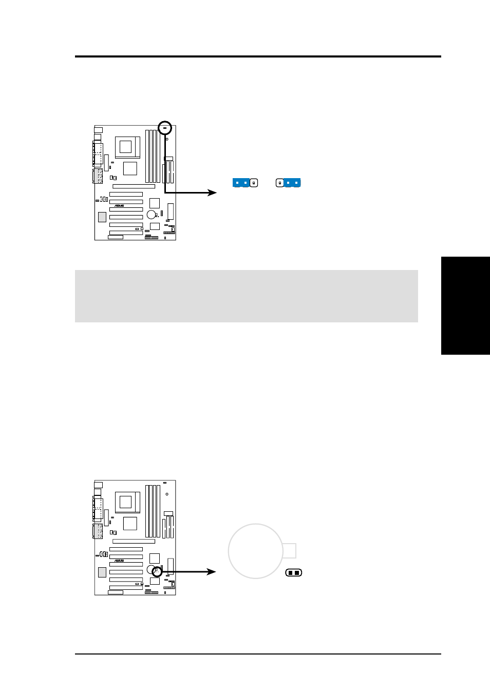
4) Voltage I/O Setting (VIO)
This jumper allows you to select the voltage supplied to the DRAM, chipset,
AGP, and PCI. Keep the jumper to its default setting Normal. When system
overclocking requires a higher voltage, set this jumper to 3.6V.
WARNING!
Using a higher voltage may help when overclocking the system but
it may shorten the life of system components. As much as possible, keep the VIO
jumper to its default setting for better system stability.
5) Clear RTC RAM
These two solder points allow you to clear the Real Time Clock (RTC) RAM in
CMOS. You can clear the CMOS memory of date, time, and system setup
parameters by erasing the CMOS RTC RAM data. The RAM data in CMOS,
that include system setup information such as system passwords, is powered by
the onboard button cell battery. To erase the RTC RAM: (1) unplug the computer,
(2) short the solder points, (3) plug and turn ON the computer, (4) hold down the key during the boot process and enter BIOS setup to re-enter data.
TUV4X VIO Setting
VIO
Normal
3.60 Volt
2 3
1 2
TUV4X
®
TUV4X Clear RTC RAM
CLRTC
Short solder points
to Clear CMOS
CR2032 3V
Lithium Cell
CMOS Power
TUV4X
®