Voltage control – Asus P5ND2-SLI User Manual
Page 101
A S U S P 5 N D 2 - S L I S e r i e s
A S U S P 5 N D 2 - S L I S e r i e s
A S U S P 5 N D 2 - S L I S e r i e s
A S U S P 5 N D 2 - S L I S e r i e s
A S U S P 5 N D 2 - S L I S e r i e s
4 - 2 5
4 - 2 5
4 - 2 5
4 - 2 5
4 - 2 5
LDT Spread Spectrum [Center Spread]
Disables or sets the Lightning Data Transport (LDT) clock generator
spread spectrum. The default setting [Center Spread] allows a
dynamic LDT frequency change of -0.25% to +0.25%.
Configuration options: [Disabled] [Center Spread]
F1:Help
↑↓
: Select Item
-/+: Change Value
F5: Setup Defaults
ESC: Exit
→←
: Select Menu
Enter: Select Sub-menu
F10: Save and Exit
Select Menu
Item Specific Help
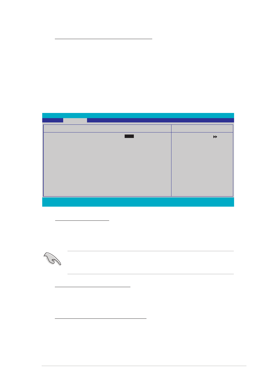
Press [Enter] to set.
Voltage Control
DRAM Voltage
[
Auto
]
Chipset Core Voltage
[+1.4V]
South Bridge SATA Voltage
[+1.5V]
CPU Termination Voltage
[1.25V]
VCore Overvoltage 100mv
[Disabled]
VCore Voltage
[Auto]
Phoenix-Award BIOS CMOS Setup Utility
Advanced
DDR2 Voltage [Auto]
Allows you to set the DDR2 operating voltage. Set to Auto for safe
mode. Configuration options: [Auto] [+1.80V] [+1.85V] [+1.90V]
[+1.95] [+2.00V] [+2.05V] [+2.10V] [+2.15V]
Chipset Core Voltage [+1.4V]
Allows you to set the chipset core voltage.
Configuration options: [+1.4V] [+1.5V]
South Bridge SATA Voltage [+1.5V]
Allows you to set the South Bridge SATA voltage.
Configuration options: [+1.5V] [+1.6V]
Refer to the DDR2 documentation before setting the memory voltage.
Setting a very high memory voltage may damage the memory
module(s)!
Voltage Control
Voltage Control
Voltage Control
Voltage Control
Voltage Control
This sub-menu allows you to set the system operating voltages. Set the
O v e r c l o c k P r o f i l e
O v e r c l o c k P r o f i l e
O v e r c l o c k P r o f i l e
O v e r c l o c k P r o f i l e
O v e r c l o c k P r o f i l e to [Manual], if you want to configure this item.