Asus M2N-VM DVI User Manual
Page 42
1-30
Chapter 1: Product introduction
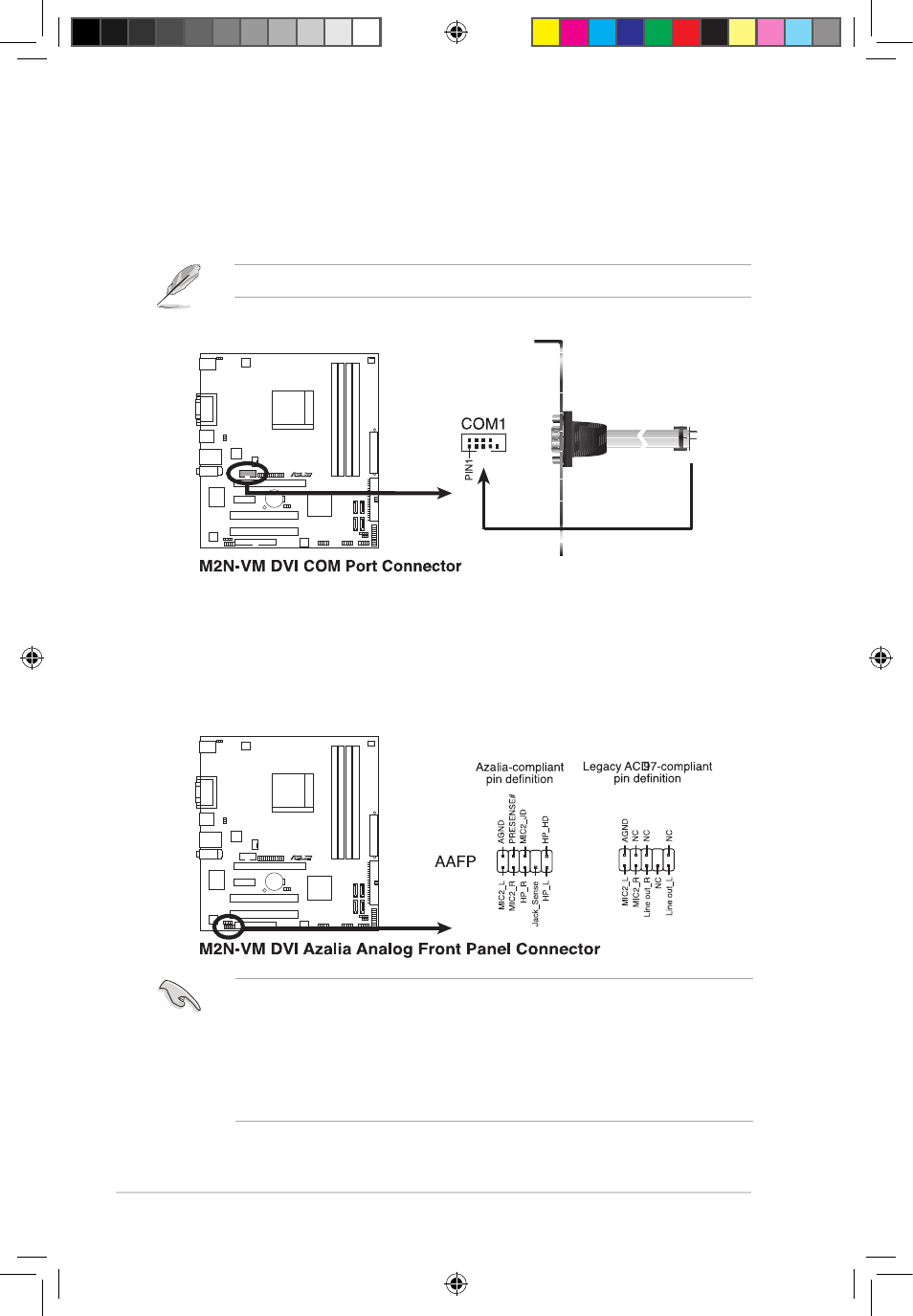
9. Serial port connectors (10-1 pin COM1)
The connector is for a serial (COM) port. Connect the serial port module
cable to the connector, then install the module to a slot opening at the back of
the system chassis.
10. Front panel audio connector (10-1 pin AAFP)
This connector is for a chassis-mounted front panel audio I/O module that
supports either �igh Definition Audio or AC`97 audio standard. Connect one
end of the front panel audio I/O module cable to this connector.
• We recommend that you connect a high�definition front panel audio module
to this connector to avail of the motherboard high�definition audio capability.
• If you want to connect a high�definition front panel audio module to this
connector, make sure that the
ke sure that the Front Panel Select item in the BIOS is set
to [�D Audio]; if you want to connect an
you want to connect an
an
AC`97
front panel audio module to
this connector, set the item to [AC97]. See page 2-29 for details.
See page 2-29 for details.
The serial port bracket (COM1) is purchased separately.
M2N-VM DVI
R
M2N-VM DVI
R
E3608_M2N-VM-DVI.indb 11
12/27/07 4:39:02 PM