2 internal connectors, F1a75-i deluxe fan connectors, F1a75-i deluxe chassis intrusion connector – Asus F1A75-I DELUXE User Manual
Page 35
1.10.2
Internal connectors
1.
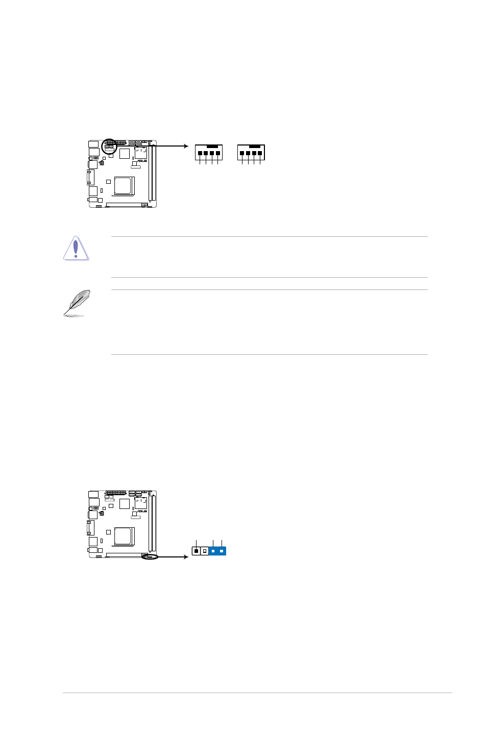
CPU and chassis fan connectors (4-pin CPU_FAN and 4-pin CHA_FAN)
Connect the fan cables to the fan connectors on the motherboard, ensuring that the
black wire of each cable matches the ground pin of the connector.
• The CPU_FAN connector supports a CPU fan of maximum 2A (24 W) fan power.
• Only the 4-pin CPU fan and chassis fan support the ASUS Fan Xpert feature.
• If you install two VGA cards, we recommend that you plug the rear chassis fan cable to
the motherboard connector labeled CHA_FAN1 for better thermal environment.
DO NOT forget to connect the fan cables to the fan connectors. Insufficient air flow inside
the system may damage the motherboard components. These are not jumpers! DO NOT
place jumper caps on the fan connectors.
F1A75-I DELUXE
F1A75-I DELUXE fan connectors
CHA_FAN
CHA
F
A
N PW
M
CPU F
AN IN
CHA
F
A
N PW
R
GND
CPU_FAN
CPU
F
A
N PW
M
CPU F
AN IN
CPU
F
A
N PWR
GND
2.
Chassis intrusion connector (4-1 pin CHASSIS)
This connector is for a chassis-mounted intrusion detection sensor or switch. Connect
one end of the chassis intrusion sensor or switch cable to this connector. The chassis
intrusion sensor or switch sends a high-level signal to this connector when a chassis
component is removed or replaced. The signal is then generated as a chassis intrusion
event.
Remove the jumper cap only when you intend to use the chassis intrusion detection
feature.
F1A75-I DELUXE
F1A75-I DELUXE Chassis intrusion connector
+5VSB_M
B
Chassis Signal
GN
D
CHASSIS
ASUS F1A75-I DELUXE
1-23