Asus P4S133 User Manual
Page 50
38
Chapter 2: Hardware information
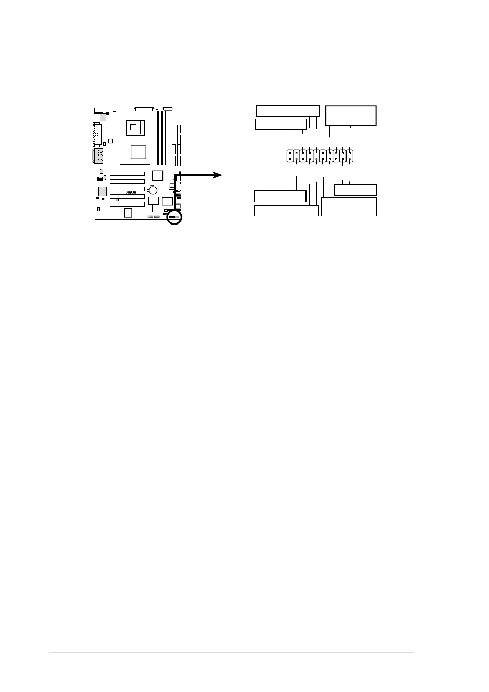
Panel Connector (20 pin PANEL)
The following diagram illustrates items 16-22:
P4S133
®
P4S133 System Panel Connectors
*
Requires an ATX power supply.
PLED
Ground
MLED
PWR
+5 V
+5V
Speaker
Speaker
Connector
Power LED
Ground
+5 V
Reset SW
SMI Lead
Message LED
ExtSMI#
Ground
Reset
Ground
Ground
ATX Power
Switch*
Keylock
Ground
Keyboard Lock
16. System Power LED Lead (3-1 pin PLED)
This connector supplies the system power LED. The LED lights up
when the system power is on, and the LED blinks when the system is
in sleep or soft-off mode.
17. Keyboard Lock Switch Lead (2 pin KEYLOCK)
This connector supplies the case-mounted key switch for keyboard
locking.
18. System Warning Speaker Lead (4 pin SPEAKER)
This connector supplies the case-mounted speaker to sound system
beeps and warnings.
19. System Message LED Lead (2 pin MLED)
This connector supports the system message LED to indicate receipt
of messages from a fax/modem. The normal status for this LED is ON,
when there is no incoming data signal. The LED blinks when data is
received. The system message LED feature requires an ACPI OS and
driver support.
20. System Management Interrupt Lead (2 pin SMI)
This connector permits switching to suspend mode, or “Green” mode,
in which system activity is instantly decreased to save power and to
expand the life of certain system components. Attach the case-
mounted suspend switch this 2-pin connector.