Asus P4S133 User Manual
Page 47
ASUS P4S133 motherboard user guide
35
P4S133
®
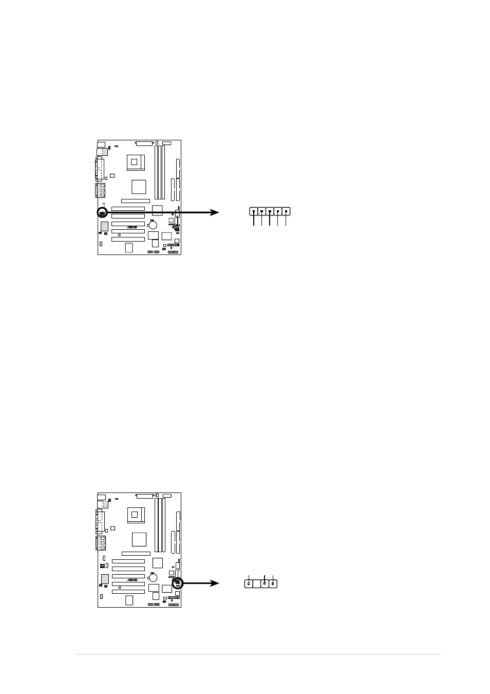
P4S133 LINE_IN Connector
ALIN1
GND
BLINE_LIN_R
ALINE_LIN_R
BLINE_IN_L
LINE_IN_L
1
11. Audio Input Line In Header (5 pin ALIN1)
This connector suports audio input on left and right stereo audio
channels. NOTE: The motherboard ships with Jumper caps over pins
1-2 and 4-5. Remove them only when making audio input
connections.
P4S133
®
P4S133 Chassis Alarm Lead
CHASSIS1
+5VSB_MB
Chassis Signal
GND
12. Chassis Open Alarm Lead (4-1 pin CHASSIS1)
This lead is intended for a chassis that supports intrusion detection.
The lead requires an external detection mechanism such as a chassis
intrusion monitor/sensor or microswitch. When any chassis component
is removed, the sensor is triggered and a high-level signal is sent to
this lead to record a chassis intrusion event. The event is then be
processed by software such as LDCM. When not using the chassis
intrusion lead, place a jumper cap over the pins to close the circuit.
Removing the jumper cap prevents the system from booting up.
- P5B Premium Vista Edition (188 pages)
- P5B (140 pages)
- P5B (56 pages)
- P5KPL-VM/1394/SI (94 pages)
- M2N68-CM (28 pages)
- P5GD1-VM (92 pages)
- P5AD2-E Premium (2 pages)
- P5GD1-VM (88 pages)
- P5AD2 Premium (8 pages)
- DELUXE A7N8X-E (114 pages)
- P5KPL-AM SE (62 pages)
- P5KPL-AM SE (40 pages)
- P5KPL-AM SE (38 pages)
- P4S8X-X (64 pages)
- P5K-VM (98 pages)
- K8V-X SE (82 pages)
- M2N68-AM SE2 (40 pages)
- P4P800 SE (16 pages)
- P4P800 SE (125 pages)
- DELUXE SERIES M3A32-MVP (176 pages)
- P5AD2 Deluxe (148 pages)
- M4A79 Deluxe (122 pages)
- A7V266-E (108 pages)
- Application Manual (4 pages)
- Application Manual (8 pages)
- Application Manual (2 pages)
- Application Manual (6 pages)
- Application Manual (9 pages)
- Application Manual (3 pages)
- Application Manual (1 page)
- Application Manual (5 pages)
- Application Manual (11 pages)
- Application Manual (10 pages)
- M4A88T-I DELUXE (44 pages)
- M4A88T-I DELUXE (70 pages)
- P9X79 DELUXE (2 pages)
- RAMPAGE IV GENE (1 page)
- P9X79 (156 pages)
- P8H61-M PLUS V3 (64 pages)
- A85XM-A (78 pages)
- M4A78L-M LE (64 pages)
- M2N68-AM (96 pages)
- M2N68-AM (62 pages)
- M2N68-AM (38 pages)
- Blitz Formula (2 pages)