Q-tech, Voltage controlled (vcxo) – Q-Tech VCXO User Manual
Page 4
4
Q-TECH Corporation - 10150 W. Jefferson Boulevard, Culver City 90232 - Tel: 310-836-7900 - Fax: 310-836-2157 - www.q-tech.com
VOLTAGE CONTROLLED (VCXO)
CRYSTAL CLOCK OSCILLATORS
-5.2Vdc & 5.0Vdc - 1kHz to 155.52MHz
Voltage Controlled (VCXO) (Revision E, August 2010 ) (ECO# 9940)
Q-TECH
CORPORATION
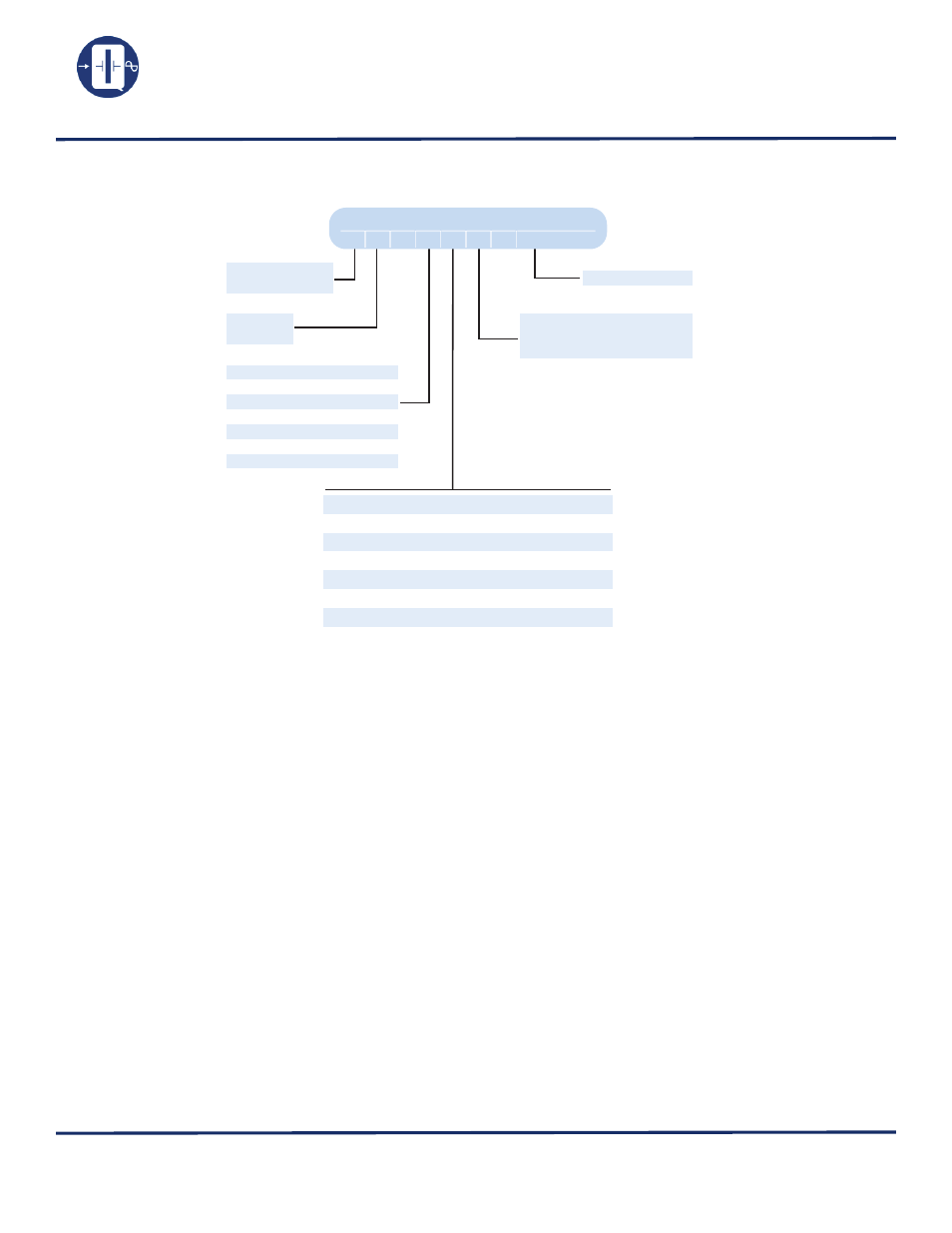
Ordering Information
Key parameters of a VCXO:
• Nominal Frequency (Fo): Output frequency at center control voltage Vc.
• Control Voltage: The available voltage range at the input of the VCXO to vary the frequency (i.e., 0 - 5V, ±4V, etc.).
• Deviation (pull range): The change in the output frequency as a function of control voltage.
• Transfer Function (sense): Direction of change in frequency as a function of control voltage.
• Temperature Range: Operating temperature range.
• Stability vs. Temperature: Percentage, or ppm, change of output frequency with respect to the temperature range at a constant
control voltage.
• Input Impedance: A measure of isolation between the VCXO internal frequency control network and the control voltage source.
• Linearity: The deviation from the best straight line slope of the frequency vs. control voltage plot.
• Modulation Bandwidth (rate): The maximum allowable rate of change of the control voltage.
Output frequency
Screened to
MIL-PRF-55310,level B
(Left blank if no screening)
1
= ± 100ppm at
0ºC to
+70ºC
4
= ± 50ppm at
0ºC to
+70ºC
5
= ± 25ppm at -20ºC to
+70ºC
6
= ± 50ppm at -55ºC to +105ºC
9
= ± 50ppm at -55ºC to +125ºC
10
= ± 100ppm at -55ºC to +125ºC
11
= ± 50ppm at -40ºC to
+85ºC
12
= ± 100ppm at -40ºC to
+85ºC
AC = ACMOS +5V
HC = HCMOS +5V
T
= TTL +5V
S
= Sine +5V
E
= 10KECL -5.2V
EH = 10KHECL -5.2V
PE = PECL +5V
Specifications subject to change without prior notice.
Packaging Options
Other Options Available For An Additional Charge
• Standard packaging in black foam (DIP)
• Standard packaging in a locked anti-static cardboard (QT24)
• Standard packaging anti-static plastic tube (QT75)
• Optional Tape and Reel
• Lead forming available on all packages. Please contact for
details.
• (*) Hot Solder Dip Sn60 per MIL-PRF 55310
• P. I. N. D. test (MIL-STD 883, Method 2020)
• Lead trimming
• J-leads attached (QT75)
QT50VAC9M-20.000MHz
QT 50 V AC 9 M - 20.000MHz
Sample part number
T = Standard
S = Solder Dip (*)
Model #
(See page 3)