Q-tech, Flat pack – Q-Tech QT28 User Manual
Page 6
6
Q-TECH Corporation - 10150 W. Jefferson Boulevard, Culver City 90232 - Tel: 310-836-7900 - Fax: 310-836-2157 - www.q-tech.com
FLAT PACK
CRYSTAL CLOCK OSCILLATORS
-5.2 to -4.5Vdc & 1.8 to 15Vdc - 0.12Hz to 200MHz
Flat Pack (Revision F, August 2010 ) (ECO# 9934)
Q-TECH
CORPORATION
Phase noise is measured in the frequency domain, and is expressed as a ratio of signal power to noise power measured in a 1Hz
bandwidth at an offset frequency from the carrier, e.g. 10Hz, 100Hz, 1kHz, 10kHz, 100kHz, etc. Phase noise measurement is made
with an Agilent E5052A Signal Source Analyzer (SSA) with built-in outstanding low-noise DC power supply source. The DC source
is floated from the ground and isolated from external noise to ensure accuracy and repeatability.
In order to determine the total noise power over a certain frequency range (bandwidth), the time domain must be analyzed in the
frequency domain, and then reconstructed in the time domain into an rms value with the unwanted frequencies excluded. This may be
done by converting L(f) back to Sφ(f) over the bandwidth of interest, integrating and performing some calculations.
The value of RMS jitter over the bandwidth of interest, e.g. 10kHz to 20MHz, 10Hz to 20MHz, represents 1 standard deviation of
phase jitter contributed by the noise in that defined bandwidth.
Figure below shows a typical Phase Noise/Phase jitter of a QT24HC, 5.0Vdc, 24MHz and QT24L, 3.3Vdc, 24MHz clock at offset fre-
quencies 10Hz to 5MHz, and phase jitter integrated over the bandwidth of 12kHz to 1MHz.
Phase Noise and Phase Jitter Integration
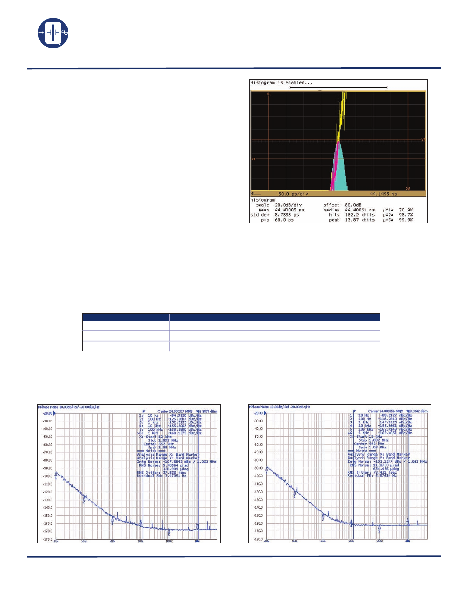
Period Jitter
As data rates increase, effects of jitter become critical with
its budgets tighter. Jitter is the deviation of a timing event
of a signal from its ideal position. Jitter is complex and
is composed of both random and deterministic jitter
components. Random jitter (RJ) is theoretically un-
bounded and Gaussian in distribution. Deterministic jitter
(DJ) is bounded and does not follow any predictable
distribution. DJ is also referred to as systematic jitter. A
technique to measure period jitter (RMS) one standard
deviation (1σ) and peak-to-peak jitter in time domain is
to use a high sampling rate (>8G samples/s) digitizing
oscilloscope. Figure shows an example of peak-to-peak
jitter and RMS jitter (1σ) of a QT24L-20MHz, at 3.3Vdc.
RMS jitter (1σ): 5.75ps Peak-to-peak jitter: 60ps
Symbol
Definition
∫
L(f)
Integrated single side band phase noise (dBc)
Sφ (f)=(180/Π)x
√
2 ∫
L(f)df
Spectral density of phase modulation, also known as RMS phase error (in degrees)
RMS jitter = Sφ (f)/(fosc.360°)
Jitter(in seconds) due to phase noise. Note Sφ (f) in degrees.
QT24HC, 5.0Vdc, 24MHz
QT24L, 3.3Vdc, 24 MHz