Part numbers – Pro Series 51016 51 Receiver User Manual
Page 4
Part Numbers:
51016
Drill 6 FT.
Bed units
Dodge Ram Pickup Truck - Full size - 1994-Present
No drilling for 8 ft. Bed units; Drill two (2) holes for 6 ft. Bed units
Does not fit with heavy duty suspensions
Rev. A
6-27-06
N51016
Sheet 4 of 5
z
2001, 2006 Cequent Towing Products
Lock Washer 1/2
Qty. (2)
Spacer 1/4 X 1.50 X 2.00
Qty. (12)
5
Bolt 1/2-13 X 2.25
Qty. (2)
Conical Washer ½
Qty. (6)
6
Hex Nut 1/2-13
Qty. (6)
7
Nut M12 X 1.75
Qty. (2)
Bolt 1/2-13 X 2.00
Qty. (4)
4
Spacer 7/16 X 1.00 X 2.00
Qty. (2)
Flanged Locknut 1/2-20
Qty. (6)
3
Bolt M12 X 1.75 X 45
Qty. (2)
9
Harden Flat Washer
Qty. (8)
2
Spacer 1/4 X 1.00 X 2.00
Qty. (4)
8
Bolt 1/2-20 X 1.50
Qty. (6)
1
Note: check hitch frequently, making sure all fasteners and ball are properly tightened. If hitch is removed, plug all holes in trunk pan or other body panels to
prevent entry of water and exhaust fumes. A hitch or ball which has been damaged should be removed and replaced. Observe safety precautions when working
beneath a vehicle and wear eye protection. Do not cut access or attachment holes with a torch.
This product complies with safety specifications and requirements for connecting devices and towing systems of the state of New York, V.E.S.C. Regulation V-5
and SAE J684.
12
13
11
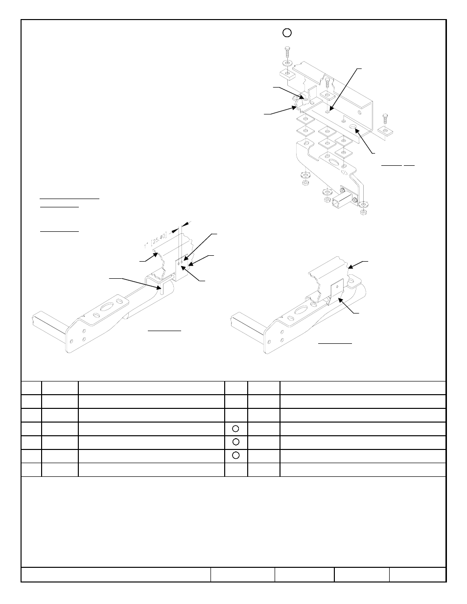
1. Remove exhaust hanger bracket from side of frame.-
Not Required after 1997.
2. Raise receiver into position centering rearmost hole over
existing hole (not large hole) at end of the frame. To clear
lip on bottom of frame, place two spacers between side
bracket and frame at each attachment point. Drill forward
hole on 6 ft. Bed units.
3. On 1999 units, the center attachment hole does not line up
with the existing hole in the vehicle frame. Enlarge hole in
the frame to match the hole in the side bracket.
4. Install 1/2-13 bolts and fasteners in each side bracket
as shown.
5. Center receiver crosstube assembly on vehicle and tighten
1/2-20 hex bolts installed as shown on page 1 to
90 lb.-Ft.(122 N*M)
6. Exhaust reinstallation – If required
8 ft. Bed units - Drill hole in exhaust bracket to reposition
bracket 1" (25.4mm) forward as shown below.
Reinstall bracket.
6 ft. Bed units - Reinstall exhaust hanger bracket.
4
8
2
4
8
6
7
6
7
6
7
13
5
5
Large existing hole
– Do Not Use
Enlarge holes for
1999 applications
Crossmember
and rivet
(location varies
by Model)
Existing hole
Exhaust hanger
bracket
Frame rail
Tailpipe support
8’ Bed units
6’ Bed units
Frame rail
Exhaust hanger bracket to
be bent inboard to clear
side bracket.
Drill hole to move
exhaust hanger bracket
forward 1” (25.40)
Tighten all 1/2-20 GR5 fasteners with torque wrench to 90 Lb.-Ft. (122 N*M)
Tighten all 1/2-13 GR5 fasteners with torque wrench to 75 Lb.-Ft. (102 N*M)
Tighten all M12 CL10.9 fasteners with torque wrench to 75 Lb.-Ft. (102 N*M)
Form: F205 Rev A 5-6-05