Caution – Aqua-Pure APIF100 User Manual
Page 13
CAUTION
To reduce the risk associated with property damage due to water leakage:
• Take care when using pliers or pipe wrenches to tighten plastic fi ttings, as damage may occur if over tightening occurs.
Typical examples of proper drain line diameters and lengths are:
1/2” ID up to 15 feet when discharge is lower than the inlet.
5/8” ID up to 15 feet when discharging is slightly higher than the inlet.
3/4” ID when drain is 25 feet away and not higher than 4 feet above control valve.
Avoid installing drain line overhead or using fl exible vinyl tubing. Use of either may result in the fi lter not operating properly in reducing iron, manganese or
turbidity. Some areas prohibit the use of fl exible drain lines. Check with the local code offi cials prior to installation to ensure you conform to local, state and
national plumbing codes.
Step 10
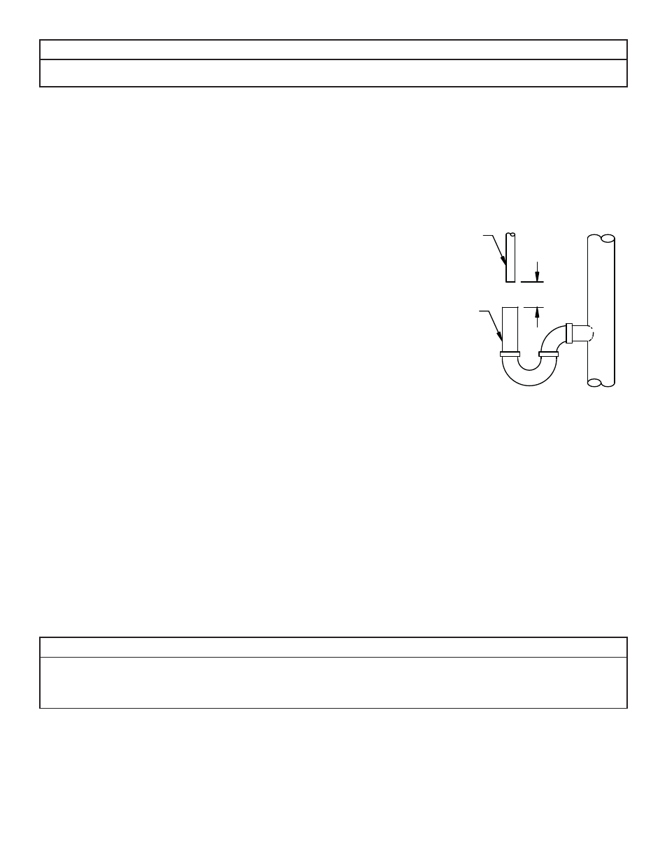
Position the DRAIN LINE over the waste drain pipe and secure fi rmly. To prevent back siphoning of
sewer water or grey water, provide an air gap of at least two inches or 2 times the pipe diameters
between the end of drain line tubing and waste drain (Figure 6). Do not raise the DRAIN LINE more
than 10 feet above the fl oor. Check with local code offi cials to ensure you conform to local, state
and national plumbing codes.
Step 11
Plug the control valve into a properly grounded 110 V, 60 Hz non switched electrical outlet. Check
with your local code enforcement offi ce to determine if it meets local codes.
Step 12
Set the time of day by referring to Page 3-8 “How to Set Time of Day”.
Step 13
Open the valve on the water supply as required to pressurize the water lines to the dwelling or fuel
source. The power to the water heater or boiler needs to be established once water has been allowed to fl ow back into the device, if it was drained at any
time during the installation. Turn back on the power or fuel source to either the water heater or boiler if it was drained at any time during the installation.
Check for leaks on all connections before leaving the job site, correct as required.
Step 14
Manually initiate regeneration of the iron and manganese reduction system by referring to the “How To Manually Initiate Immediate Regeneration” sec-
tion of Control Valve settings on Page 3-8.
Step 15
Once the valve is in the backwash position (C1 appears on the display) slowly open the inlet side of the bypass valve to allow water to fl ow into the tank.
Water should start to fl ow into the drain. Allow for any air that might have been trapped to leave the fi lter and go to drain. This will be detected by changes
in noise in the drain line or is visible in the semi-transparent tubing. Once the air is entirely gone slowly increase the water fl ow to drain by opening the inlet
side of the bypass valve until fully open. Refer to Figure 3 for correct positioning. At the end of C1 position the water should be clear. If not, allow the valve to
complete the manual regeneration process and initiate once again. It is very important to allow the unit to purge all fi nes to the waste drain from the media
in the tank prior to using the water. Once the fl ushing process has been completed you now can open the outlet side of the bypass valve to allow for fi ltered
water to fl ow into the dwelling.
IMPORTANT NOTES
Due to the nature of the iron reduction media, on start up it sometimes requires 2 or 3 days for the iron and manganese reduction system to reduce
Iron and Manganese below staining levels. Do not be alarmed if this occurs. During the initial start up and subsequent fi rst couple automatic regenera-
tion cycles, a small amount of fi ne white and beige media may be observed in the drain water and or drain area. This is normal and benefi cial for the
effi cient operation of your iron and manganese reduction system.
Step 16
The frequency of backwash is factory preset at every 4 days. If the iron content is greater than 5 ppm, is red water or bacterial iron the unit should be washed
more frequently. See tables to determine the frequency. Also if the water has tannin-lignin or hydrogen sulfi de present, the fi lter should backwash every day.
Refer to Section 4 for backwashing instructions and frequency.
3-5
AIR GAP
2" REF
EQUIPMENT
DRAIN LINE
DRAIN
Figure 6: Drain