Aqua-Pure APIF100 User Manual
Page 11
Step 3
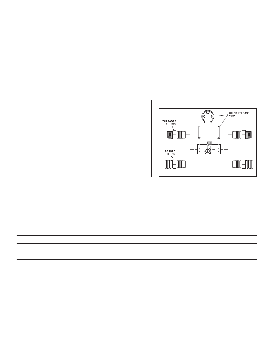
Cut main supply line as required to fi t hydro-charger in plumbing between well pump and pressure tank (hydro-charger may be installed in a vertical or
horizontal position). The hydro-charger has been supplied with both 1” threaded and 1” barbed (insert) fi ttings to allow for installation with various types of
piping materials. When using the threaded nipples, use thread tape only. When using barbed (insert) fi ttings, appropriate pipe clamps must be used. Once
installed the quick release nipples allow the hydro-charger to be rotated, so the air draw adjustment screw is accessible for adjustment by a small bladed
screwdriver. Allow at least 10 inches of straight run of 1” pipe on both INLET and OUTLET side of the hydro-charger. Refer to Figure 2 for correct assembly.
The quick release nipples also act as a union to facilitate the hydro-charger removal, inspection and cleaning as needed. With an installation on PVC pipe
and copper tubing it may require the addition of a plumbing union to aid in removal from the plumbing due to the rigidity of that type of material. Make
certain the directional arrows on the hydro-charger point towards the pressure tank and the pressure control switch is located on the pressure tank side
of hydro-charger as in Figure 1. Rapid cycling of pump may occur if the pressure control switch is located on well side. If a check valve is located between
hydrocharger and pressure tank, it may prevent the hydro-charger from performing properly. Relocate to well side of hydro-charger.
Step 4
Turn back on the power to the well pump and pressurize the water lines to allow for adjustment of the hydro-charger. Check for leaks and adjust as necessary.
IMPORTANT NOTES
• Do not apply heat near
hydro-charger
, as damage may occur. On badly scaled, older
plumbing systems, it may be advantageous to install a WYE STRAINER to help pre-
vent plugging of the hydro-charger nozzle with scale or debris. The use of a WYE
STRAINER must precede the hydrocharger on the inlet side by a MINIMUM OF
10”.
• If existing water system includes a captive-air type pressure tank (bladder) and it is
desirable to install an additional air to water type with an air release (not as a split
steam type installation) install an air to water type pressure tank between the
hydro-
charger
and the existing captive air type pressure tank.
• Before proceeding with hydro-charger installed, re-verify adequate pump-
ing rate pumping by following the procedure described in SECTION 2. After
verifi cation of adequate fl ow, depressurize system as described previously.
• If installation is to be split streamed prior to tank or is it a public water supply
(see fi gure 1), or refer to special instructions on page 3-11.
Step 5
Set hydro-charger by following the following steps:
a) Open nearest faucet until well pump starts, then close faucet.
b) Place a fi nger lightly over the SUCTION PORT (Figure 4). A slight suction should be detected for approximately ONE THIRD (1/3) of pumping cycle time. (Do not
confuse with ONE THIRD (1/3) of pressure range).
c) If suction is too short, increase by turning air adjustment screw (Figure 4), CLOCKWISE. To decrease duration, turn COUNTER-CLOCK WISE.
d) Repeat steps (a) through (c) until proper setting is obtained. The optimum cycle time is 60 seconds or more, with
an air draw of 20 seconds minimum. Position DRAIN LINE over drain and secure fi rmly. To prevent back-siphoning of sewer water, provide an air gap of at
least 2 inches or 2 pipe diameters between end of drain hose and drain (Figure 6). Do not raise DRAIN LINE more than 10 ft. above fl oor.
IMPORTANT NOTE
When the duration of the suction is too long, the cold water may have a milky appearance caused by excess air in the water system. Correct this condi-
tion by reducing the duration of suction. This condition is commonly associated with bladder type pressure tanks. In extreme cases where elimination
of excess air prevents system from performing satisfactorily, it may be necessary to install an air to water pressure tank with an air release valve.
Step 6
Turn off the electrical source to the water well pump or the close the water shut off valve on a municipal water supply to the dwelling once again. Depressurize
the water system by opening the nearest faucet to drain water from the water system in order to allow the installation of the iron and manganese reduction
system.
Step 7
Determine location and cut the water line on the supply side of the pressure tank as required to fi t the plumbing to the control valve connection fi ttings.
You may want to install a separate three valve bypass prior to the control valve in case the supplied bypass valve requires maintenance in order to provide
undisturbed water use.
3-3
Figure 2: Hydro-Charger Installation