Caution – Aqua-Pure CSX200 User Manual
Page 9
3-2
Step 1
CAUTION
CAUTION
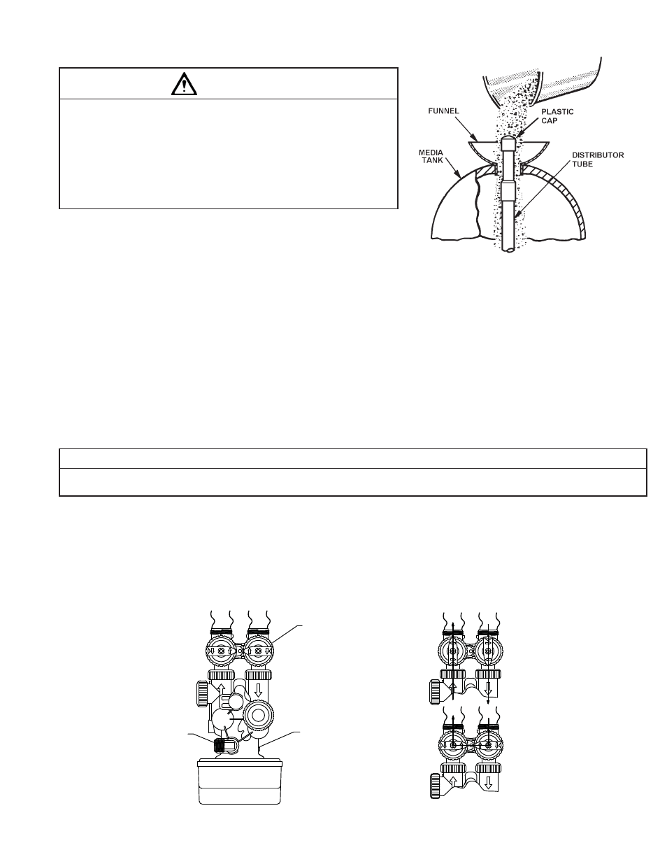
To reduce the risk associated with skin, eye, and respiratory tract irritation from gravel
and fi lter media during installation:
• Gravel and several types of fi lter media may be used in this product, depending upon the
application. During installation, dust may cause irritation to skin, eyes, and respiratory tract.
• Utilize a NIOSH-approved dust fi lter mask, protective gloves, and appropriate eye protection
when handling and pouring gravel and fi lter media.
• To request an MSDS relating to the media included with this product, call 203-238-8965 or go
to www.3M.com, select country, and use the search engine to search MSDS. For emergen-
cies, call 800-364-3577 or 651-737-6501 (24 hours).
a)
Remove the control valve by rotating the valve head assembly to the left or counter-clock-
wise and set aside to reassemble after media is loaded into the tank. Before loading the
MEDIA into the tank, the distributor tube must be all the way to the bottom of the tank. IThe
distributor should be removed and the gravel dumped out and saved. The distributor should
then be replaced in the empty tank making sure it rests on the bottom. Use the centeringtool
provided to hold the riser tube (not shown) in the center and prevent media from entering
the distributor tube. Material lodged in the distributor tube can enter the control valve, thus
damaging it. First pour the gravel removed earlier back into the media tank, followed by the media. Using a water hose or clean pail fi ll the media tank
with water to just short of the threads on media tank.
b)
Lubricate the o-ring on the adapter base with silicone grease. Reinstall the control valve making sure the riser tube fi ts into the valve body tube adaptor
protruding from the bottom of valve body, being careful not to pinch the o-ring.
c)
Locate the bypass valve assembly and connection fi ttings shipped with the sulfur reduction unit. Assemble the connection fi ttings and attach to the bypass
valve as shown in Figure 3.
Step 2
Shut off all water at main supply valve. On a private well system, turn off power to the pump and drain the pressure tank. Make certain pressure is relieved
from the complete system by opening the faucet closest to the system.
CAUTION
To reduce the risk associated with property damage due to water leakage:
• SHUT OFF FUEL OR ELECTRIC POWER SUPPLY TO WATER HEATER after water is shut off.
Step 3
The feed pump and solution tank require assembly prior to use (Figure 4).
a)
Unpackage feed pump.
b)
Install injection assembly in water supply line prior to pressure tank and pressure switch. Note: The position of the installation position and direction of
the injection assembly as shown in Figure 4.
Figure 2. FILLING MEDIA TANK
OFF
OFF
OFF
OFF
OFF
OFF
OFF
OFF
Supply Water
Enters
Treated
Water Exits
NORMAL OPERATION
BYPASS VALVE
IN
OUT
CONTROL
VALVE BODY
DRAIN LINE FLOW
CONTROL ASSEMBLY
OFF
OFF
OFF
OFF
Supply (Untreated)
Water Exits
BYPASS OPERATION
Supply Water
Enters
Figure 3. FILTER ASSEMBLY TOP VIEW