Aqua-Pure CSX200 User Manual
Page 10
c)
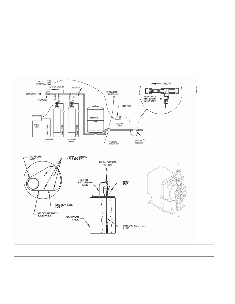
Attach bleed valve to top of feed pump head. The white nut on discharge (top) of feed pump must be removed. The bleed valve can now be attached,
make sure to use o-ring provided.
d)
Lower the precut suction line tubing assembly (clear tube with foot valve assembly and ceramic weight) into the opening of the solution tank. Feed the
tubing into the proper hole in the top of the solution tank. The foot valve assembly when properly placed should be about 1” to 1.5” off the bottom of the
solution tank.
e)
Mount the feeder pump to the top of the solution tank. Before securing the feeder pump to the solution tank, remove the compression nut from the check
valve assembly and slide over suction tubing to determine the approximate length of the tubing. Trim as necessary. Secure tubing to check valve assembly
by tightening the fi tting using your hands only.
f)
Attach bleed return line (short white tubing) to connection on side of bleed valve and feed down into solution tank through pre-drilled hole.
g)
Attach discharge line (remaining long white tubing) to connection on top of bleed valve. Cut and attach this line to the Injection Assembly installed in Step 3b.
h)
The installation of the feed pump requires a means to disconnect the feed pump from the power supply should service or maintenance to the feed pump
be required. While not required, it is suggested that the voltage of the feed pump match the voltage of the water pump. The feed pump that is shipped
with the standard unit is rated for 120 volt while most well pumps are rated for 240 volts.
IMPORTANT NOTE
Electric feed pump must be connected to the same voltage as the well pump or power supply. (Do not cut feed pump power cord.)
Step 4
Cut main supply line as required to fi t plumbing to inlet and outlet of bypass valve.
Step 5
Attach plumbing. DO NOT apply heat to any fi ttings connected to bypass or control valve, as damage may result to internal parts or connecting adapters. Make
certain water fl ow enters through inlet and discharges through outlet.
3-3
Figure 4. FEEDER SYSTEM SCHEMATIC