Pin accessory connector - part numbers – Ocean Optics USB2000-FLG User Manual
Page 31
C: Specifications
170-00000-FLG-02-201009
25
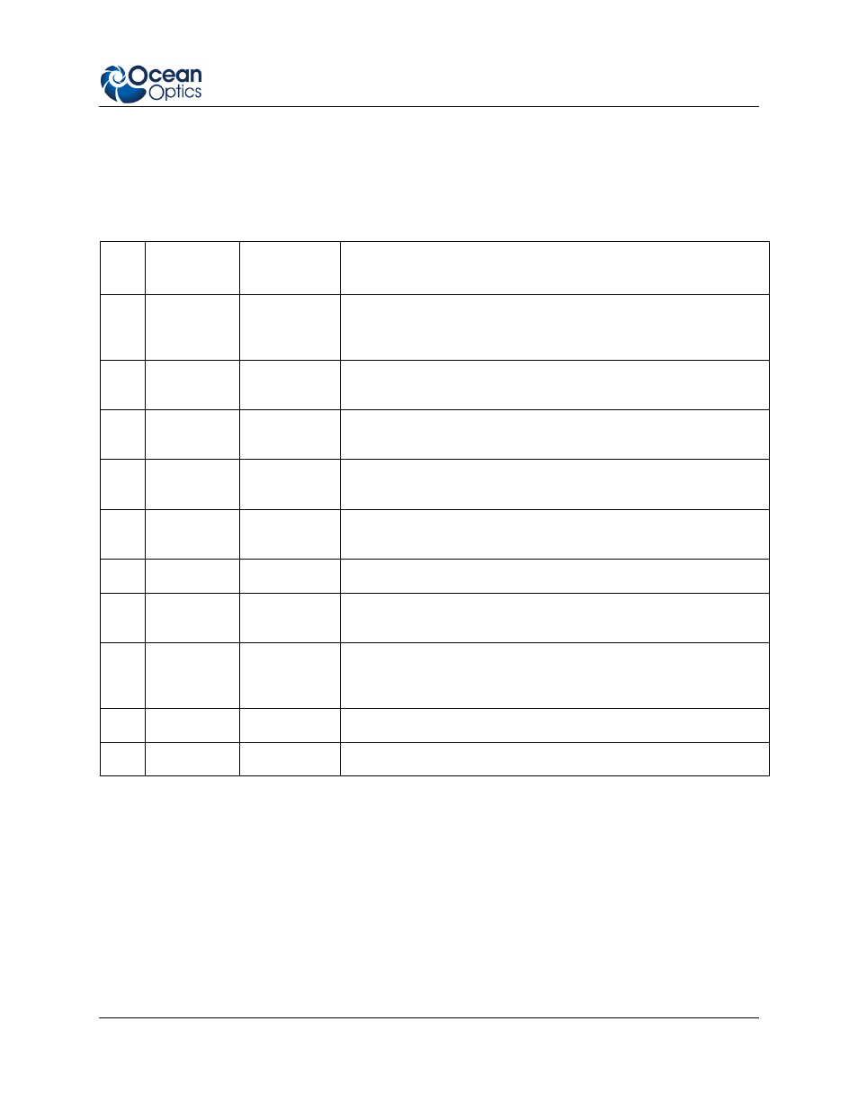
10-Pin Accessory Connector – Pin Definitions and
Descriptions
The following table contains information regarding the function of each pin in the USB2000-FLG’s 10-
Pin Accessory Connector:
Pin
#
Function
Input/Output
Description
1
V
CC
, V
USB
,
or 5V
IN
Input or
Output
Input power pin for USB2000-FLG – When operating via USB, this
pin can power other peripherals – Ensure that peripherals comply
with USB specifications
2
RS232 Tx
Output
RS232 transmit signal – Communicates with a computer over DB9
Pin 2
3
RS232 Rx
Input
RS232 receive signal – Communicates with a computer over DB9
Pin 3
4
Lamp
Enable
Output
TTL signal driven Active HIGH when the Lamp Enable command
is sent to the spectrometer
5
Continuous
Strobe
Output
TTL output signal used to pulse a strobe – Divided down from the
master clock signal
6
Ground
Input/Output
Ground
7
External
Trigger In
Input
TTL input trigger signal – See External Triggering Options
document for info
8
Single
Strobe
Output
TTL output pulse used as a strobe signal – Has a programmable
delay relative to the beginning of the spectrometer integration
period
9
I
2
C SCL
Input/Output
The I
2
C clock signal for communications to other I
2
C peripherals.
10
I
2
C SDA
Input/Output
The I
2
C Data signal for communications to other I
2
C peripherals.
10-Pin Accessory Connector - Part Numbers
The part numbers for the 10-pin accessory connector on the USB2000-FLG Spectrometer are as follows:
The connector is a Samtec Part Number IPT1-105-01-S-D-RA.
The mating right-angle connector is a Samtec Part Number IPS1-105-01-S-D-RA.
If you are customizing your USB2000-FLG Spectrometer system or configuring External Triggering, you
may need these part numbers to complete your setup.