Pin j2 accessory connector - part numbers – Ocean Optics HR4000CG-UV-NIR User Manual
Page 33
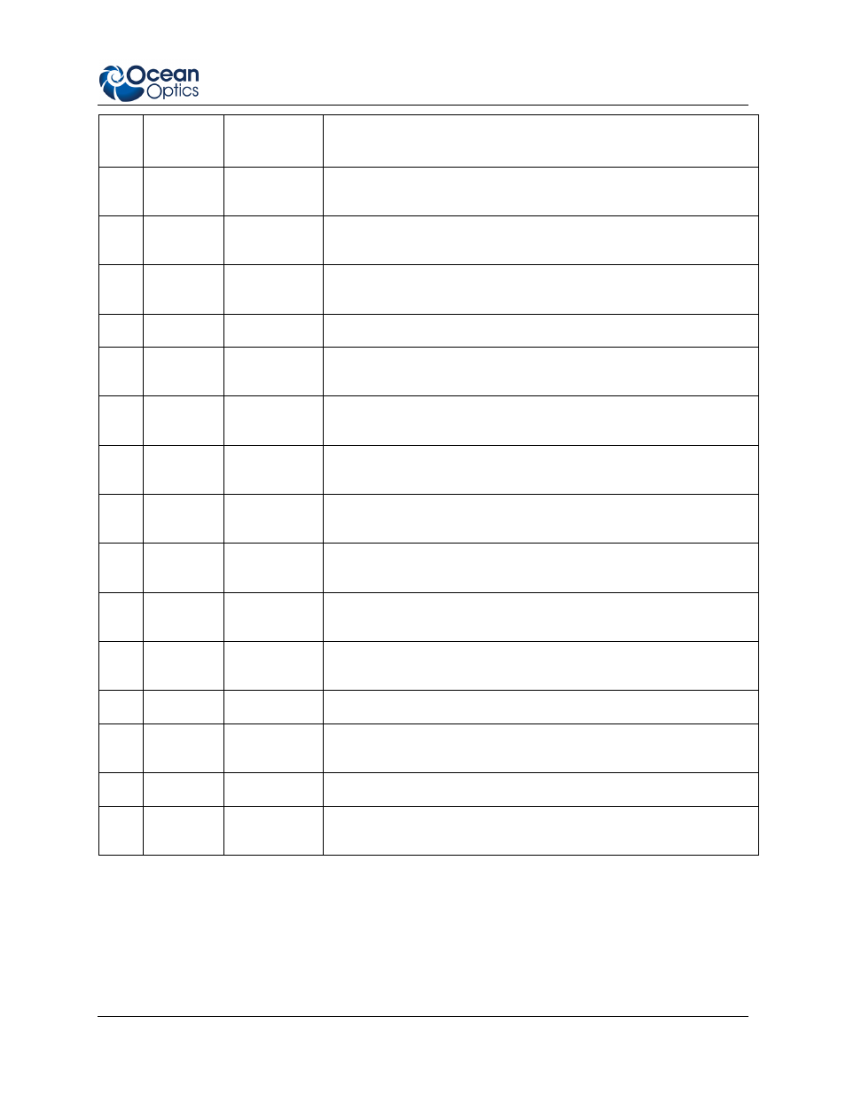
B: HR4000 Specifications
Pin
#
Function Input/Output Description
16
GPIO (4)
Input /Output
General purpose software-programmable, digital input/output
(channel number)
17
Single
Strobe
Output
TTL output pulse used as a strobe signal – Has a programmable
delay relative to the beginning of the spectrometer integration period
18
GPIO (5)
Input/Output
General purpose software-programmable, digital input/output
(channel number)
19
SPI Clock
Output
SPI clock signal for communication to other SPI peripherals
20
Continuou
s Strobe
Output
TTL output signal used to pulse a strobe – Divided down from the
master clock signal
21
SPI Chip
Select
Output
SPI Chip/Device Select signal for communication to other SPI
peripherals
22
GPIO (6)
Input/Output
General purpose software-programmable, digital input/output
(channel number)
23
Analog In
(0-5V)
Input
13-bit analog-to-digital input with a 0-5V range
24
Analog
Out (0-5V)
Output
9-bit programmable output voltage with a 0-5V range
25
Lamp
Enable
Output
TTL signal driven Active HIGH when the Lamp Enable command is
sent to the spectrometer
26 GPIO
(7) Input/Output
General purpose software-programmable, digital input/output
(channel number)
27 Ground Input/Output Ground
28 GPIO
(8) Input/Output
General purpose software-programmable, digital input/output
(channel number)
29
Ground
Input/Output
Ground
30 GPIO
(9) Input/Output
General purpose software-programmable, digital input/output
(channel number)
30-Pin J2 Accessory Connector - Part Numbers
The part numbers for the 30-pin accessory connector on the HR4000 Spectrometer are as follows:
• The connector is Pak50™ model from 3M Corp. Headed Connector – Part Number
P50–030P1–RR1–TG.
210-00000-000-02-0908
25