Wiring (continued) figure 3-5, Logic board power board – Factory Direct Hardware LCN 9531 User Manual
Page 6
Page 6 of 14
740100-00(5)
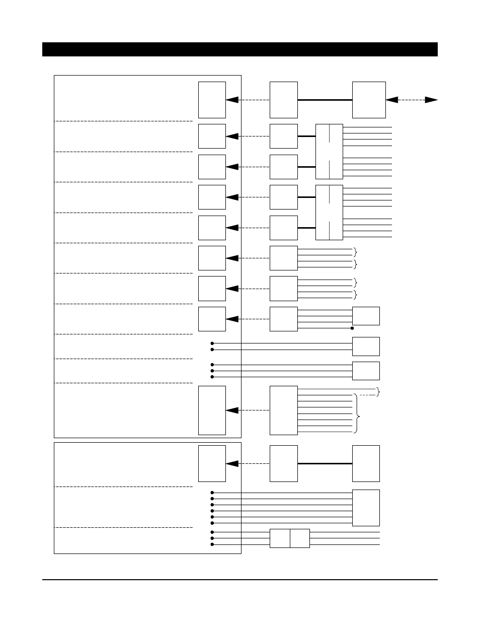
3. WIRING (continued)
Figure 3-5
Black, 24 VAC
Red, 24 VAC
White, Activate
Green, Ground
Black, 24 VAC
Red, 24 VAC
White, Slowdown
Green, Ground
Black, 24 VAC
Red, 24 VAC
White, Activate
Green, Ground
Black, 24 VAC
White, 24 VAC
Yellow, Activate
Gray, Ground
Black, 24 VAC
White, 24 VAC
Yellow, Activate
Gray, Ground
Blue, Carpet Safety
Gray, Ground
Yellow, Activate
Violet, Slowdown
Orange
Black
Red
Green
Black
Bodyguard
JST-type
connector
To DMSS
(master;
safety side)
To DMSS
(master;
approach side)
To DMSS
(companion;
safety side)
To DMSS
(companion;
approach side)
To existing cable
710057 (old part
No. 81276)
To 3-position
switch (if used)
To motor cable of
companion operator
(use only for second
door of simultaneous
pair of doors)
To motor cable of
master operator
(always use for
single door)
Bodyguard cable
to Bodyguard
sensor
Cable
761468
Cable
761464
Cable
761464
Cable
761469
Cable
761465
To locking device
(see page 7 for
sample wiring)
Cable
761466
Cable
761463
Retrofit
only
If used
If used
If used
If used
If used
If used
If used
If used
If used
Activate: Initiates a door opening cycle
Bodyguard (master; safety side): Prevents
door from opening; holds open door in open
position (uses door state data from control box
to ignore door movement while opening/closing)
DMSS (master; safety side): Prevents door from
opening, and slows an opening door
Activate: Initiates a door opening cycle
(operates identically to P6 and is provided as
a convenience if 2 activations are used)
DMSS (master; approach side): Initiates a door
opening cycle if activated while door is closing
AC Input: 120 VAC
Companion Motor Power: Companion motor
power (use only for second door of simultaneous
pair or independent pair of doors)
Master Motor Power: Master motor
power (use for single door)
3-Position Switch: OFF, AUTO, HOLD
Locking Interface: Power output and relay
contacts for locking devices; Power Boost
disable input
Breakaway: Disables operator inputs when
Breakaway switch is active
DMSS (companion; safety side): Prevents door
from opening, and slows an opening door
DMSS (companion; approach side): Initiates a
door opening cycle if activated while door is closing
Retrofit Accessories: Accesses older model
Activate, Slow/Stop, and Carpet Safety inputs
P1
P2
P3
P4
P5
P6
P7
P8
P10
P5
LOGIC BOARD
POWER BOARD
To normally closed
Breakaway switch
or jumper 81269
White, 24 VAC
White, 24 VAC
Black, Hot AC
White, Neutral AC
Green, Earth Ground
To 120 VAC
Black, 24 VAC
Red, 24 VAC
White, Slowdown
Green, Ground
DMSS
harness
761467
Safety
Approach
Safety
Approach
Safety
Approach
Safety
Approach
on-board
connector
on-board
connector
on-board
connector
on-board
connector
on-board
connector
on-board
connector
on-board
connector
on-board
connector
on-board
connector
on-board
connector
permanent
connections
permanent
connections
permanent
connections
permanent
connections
DMSS
harness
761467
Activate cable
To normally open Activate contacts
Activate cable
To normally open Activate contacts
Used only for powered activation device
Used only for powered activation device
Blue, Power Boost disable
Black, Ground
Violet, Relay NO
Gray, Relay COM
Brown, Relay NC
Green, 5 V
To normally open
Power Boost
disable contacts
Ground