Factory Direct Hardware LCN 9531 User Manual
Page 5
740100-00(5)
Page 5 of 14
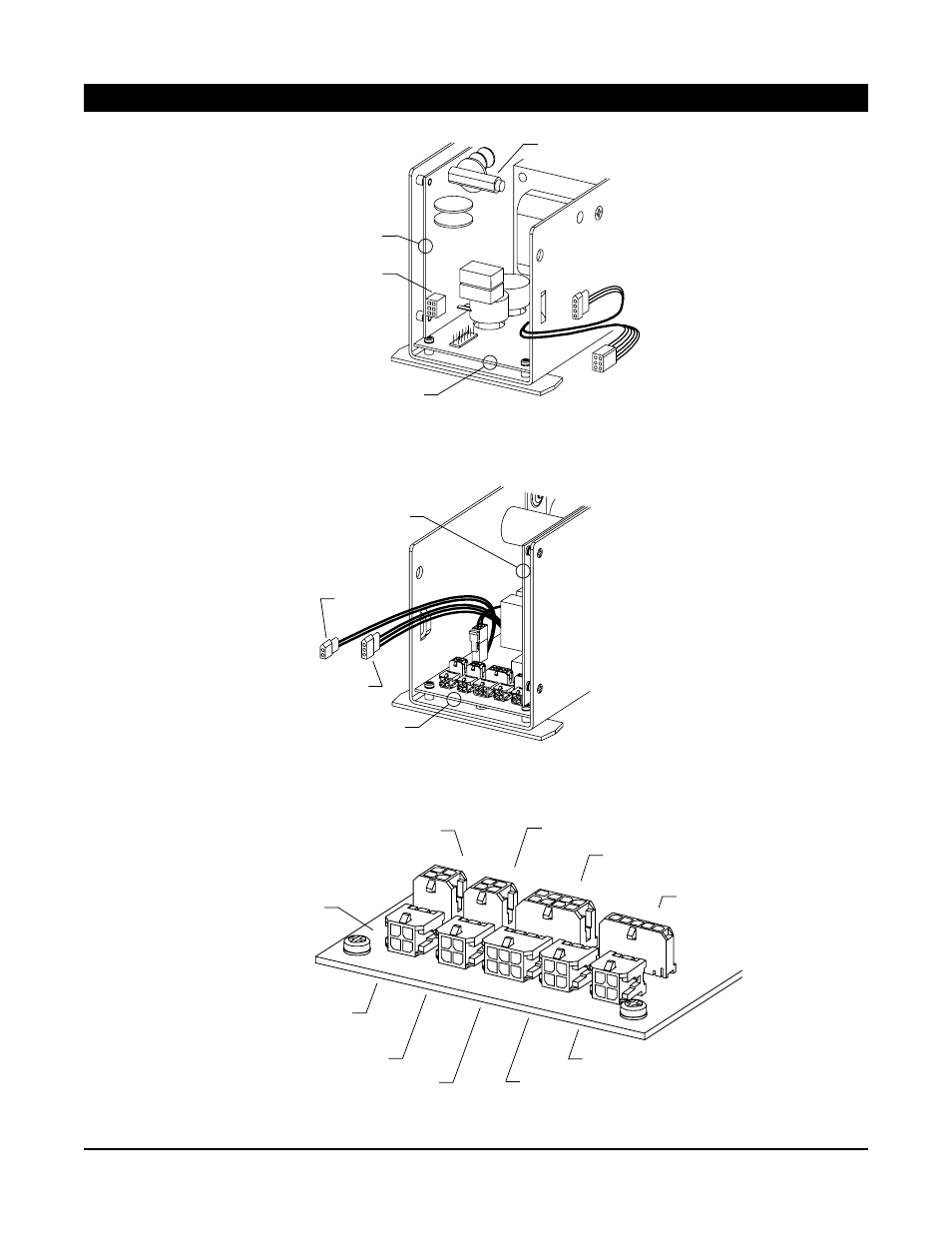
Figure 3-2. Control box power board connectors.
3. WIRING (continued)
Figure 3-3. Control box logic board connectors.
Figure 3-4. Closeup of control box logic board connectors.
P5
P3
P2
P1
P6
P7
P4
P 10
P8
DMSS (companion; safety side)
Activate
Activate
DMSS (master; safety side)
DMSS (master; approach side)
DMSS (companion; approach side)
LOGIC BOARD
Companion
motor power
(P5)
POWER
BOARD
LOGIC BOARD
AC fuse, 120 VAC
2.5 A time-delay
Master motor
power
AC
power
Bodyguard (safety side)
Breakaway
3-position
switch
POWER BOARD
LOGIC BOARD
See Figure 3-4 for
closeup of control
box logic board
connectors
Locking Interface and
Power Boost disable input
Retrofit
Accessories
See also other documents in the category Factory Direct Hardware For Home:
- Hansgrohe 14413 S (12 pages)
- Hansgrohe 11443 Axor Urquiola (28 pages)
- Hansgrohe 16542 Axor Montreux (1 page)
- Hansgrohe 31314 Metris C (1 page)
- Hansgrohe 42134 Axor Montreux (1 page)
- Hansgrohe 10882 Axor Starck (8 pages)
- Delta 3585LF-MPU (6 pages)
- Delta 45072 (1 page)
- Delta 591T0250 (6 pages)
- Brizo 69556-BB Traditional (1 page)
- Brizo 69980 RSVP (4 pages)
- Von Duprin EL9927EOF (4 pages)
- Delta 25996LF (6 pages)
- Delta 81T261-6 (1 page)
- Brizo 693520 European (2 pages)
- Delta 45371 (1 page)
- Delta 79224 Addison (1 page)
- Delta 55531 Universal (2 pages)
- Hansgrohe 27835 Axor Carlton (12 pages)
- Hansgrohe 42035 Axor Montreux (1 page)
- Delta 45160 (1 page)
- Hansgrohe 18425001 Axor Massaud (1 page)
- Hansgrohe 31730001 (12 pages)
- Delta 73846 Lahara (2 pages)
- Von Duprin 3347AEOF (16 pages)
- Pegasus 87390 Bamboo (2 pages)
- Brizo 85785 Charlotte (6 pages)
- Delta 500-WCS-DST (12 pages)
- Delta 144996 Windemere (8 pages)
- Delta 600T050 (1 page)
- Brizo 691885 Charlotte (1 page)
- Hansgrohe 10120 (8 pages)
- Hansgrohe 27479 ShowerPower (12 pages)
- Hansgrohe 39148 (8 pages)
- Delta 15960T-DST (44 pages)
- Delta 590TP0850 (2 pages)
- Delta 25938LF (6 pages)
- Delta 3555LF-216 (6 pages)
- Hansgrohe 10030 (4 pages)
- Delta 56302 Universal (2 pages)
- Pfister 001-9110 01 Series (14 pages)
- Delta 41224 (4 pages)
- Hansgrohe 34016 (12 pages)
- Brizo 69918 RSVP (2 pages)
- Pfister 007-312 07 Series (8 pages)