10 synchronous setup – Crown Audio IQ-P.I.P.-SLM User Manual
Page 21
Page 21
IQ–P.I.P.–SLM Programmable Input Processor with Load Monitoring for IQ Systems
Reference Manual
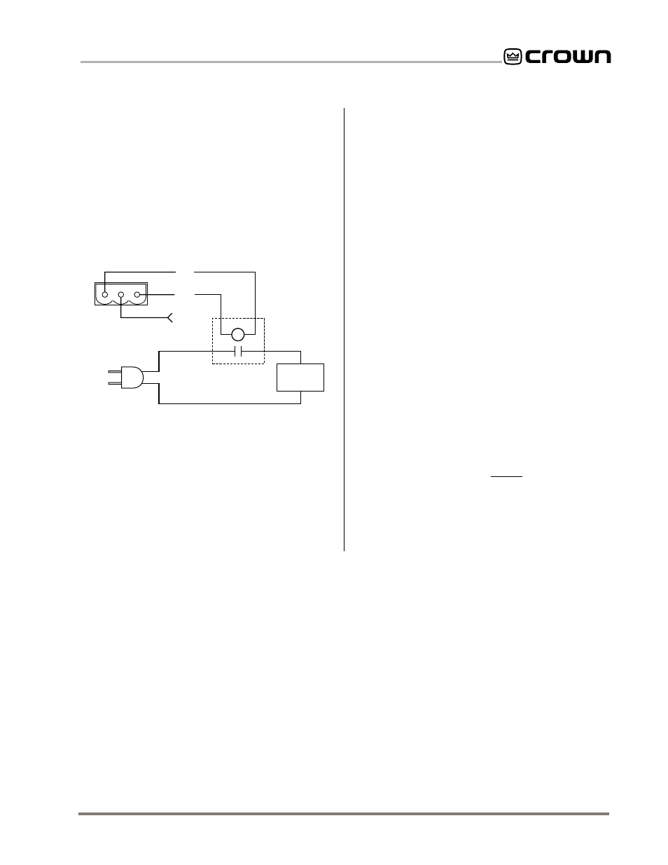
AUX
CONNECTOR
GND
+15 V
AUXILIARY
EQUIPMENT
110 VAC
SOLID
STATE
RELAY
(C 8063-3)
+
–
INPUT
Fig. 4.11 A Sample AUX Output Circuit
channels have failed a test. By reversing the logic, the
AUX output will not send a pass signal when the unit is
turned off or has no power.
4.9.3 Controlling External Devices (AUX Output)
There are many other possible uses for the AUX out-
put. For example, it can be used to turn on auxiliary
cooling fans. To do this the +15 VDC AUX output would
be used to close a relay. The relay would then turn the
fans on or off. This principal is illustrated in Figure 4.11
below:
devices can be synchronized so they function in uni-
son as a group. At least one
IQ–SLM-8 must be active
in the
IQ System in order to configure the system in
Sync mode. Here are the steps for synchronizing mul-
tiple
IQ–P.I.P.–SLMs and IQ–SLM-8s:
1 Select one of the
SLM-8s and use its Generator
Out to insert the test signal upstream of all
IQ–
SLM-8 and IQ–P.I.P.–SLM monitor points in the
audio system.
2 Set the “Generator” and “Sweep” settings of all
SLM P.I.P.s and components so they are all the
same.
3 Turn on the “Sync” control of each unit.
After the above preparations have been made, there
are two ways to generate a synchronized test. The first
way is to use the IQ software’s “All Start” command to
simultaneously initiate a test with all units. Of course,
this requires that all units be connected to an
IQ Sys-
tem. Incidentally, you can stop a test that is in progress
with the “All Abort” command.
The second way to generate a synchronized test is with
the AUX input. This enables you to perform synchro-
nized testing with stand-alone units that are no longer
connected to an
IQ System. To use this method you will
need to turn on the AUX In Trigger setting when the
units are being configured before they are discon-
nected from the
IQ System. Then you will need to con-
nect the AUX inputs of all units to the same trigger
circuit (a +5 to +15 VDC logic circuit as described in
Section 4.7.2). When the AUX inputs sense a logic high,
the units will start a test. To abort a test, simply send a
second logic high.
Note: A Crown part number is provided in Figure 4.11
for a suitable solid-state relay (C 8063-3). Contact your
local Crown representative or the Crown factory Parts
Department (219-294-8200) to order.
4.10 Synchronous Setup
In a large audio system it may be desirable to use the
IQ–P.I.P.–SLM with one or more IQ–SLM-8s and/or IQ–
P.I.P.–SLMs. When this is done, these load-monitoring
OUT