8 a closer look at audio signal wiring – Crown Audio IQ-P.I.P.-SLM User Manual
Page 19
Page 19
IQ–P.I.P.–SLM Programmable Input Processor with Load Monitoring for IQ Systems
Reference Manual
Figure 4.5 shows how the output of the
IQ–P.I.P.–SLM is
wired to an IQ component with a similar connector.
Wiring the output of a similar IQ component back to the
input of the IQ–P.I.P.–SLM is simply the reverse.
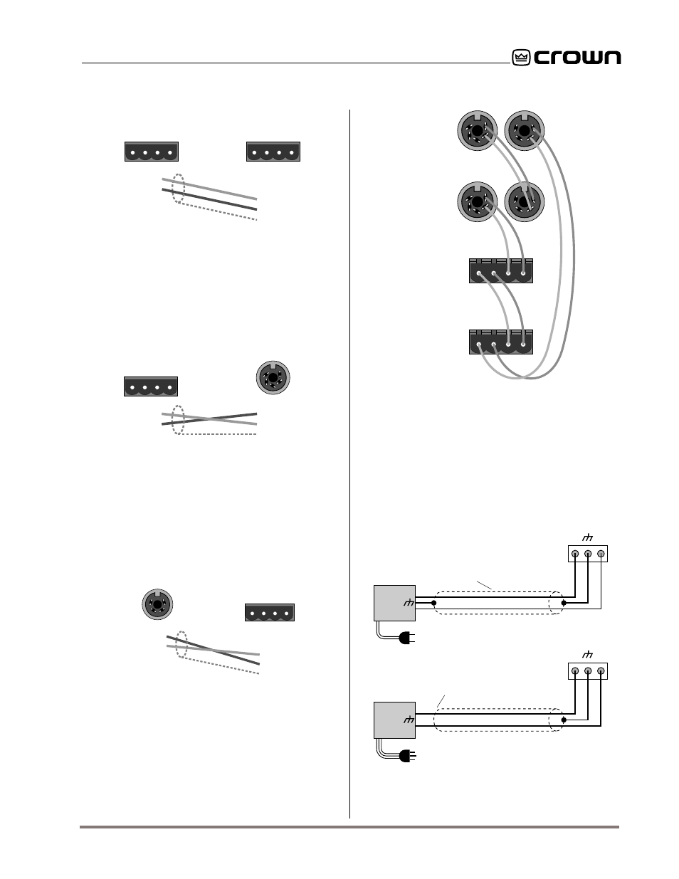
4.8 A Closer Look at Audio Signal Wiring
Balanced 3-pin removable Eurostyle barrier block con-
nectors are provided for audio input connection. The
audio cables should be wired in one of the following
manners (see Figure 4.9):
INPUT
INPUT
2-wire line cord
(or battery power)
Note: If two or more channels with
the same input ground reference
are driven from the same
floating source, connect
only one shield to the
source chassis.
Floating
source
–
+
3-wire grounded line cord
(or other ground connection)
Output
Shield not connected
at this end
Grounded
source
–
+
Output
+
–
+
–
Fig. 4.9 Audio Input Wiring
The next two figures show how to connect the
IQ–P.I.P.–
SLM to IQ components with different connectors. Figure
4.6 shows how to connect the
IQ–P.I.P.–SLM to an IQ
component with a DIN input connector.
1 Input (–)
2 Input (+)
3 GND
4 Not used
5 Not used
Output (+)
Output (–)
Input (+)
Input (–)
2
5
3
4
1
Optional Shield
IQ Component Input
OUT
IN
+ – + –
IQ–P.I.P-SLM
Output
Output (+)
Output (–)
Input (+)
Input (–)
GND Lug
GND 1
Output (+) 2
Not used 3
Not used 4
2
3
4
1
Optional Shield
IQ Component Output
OUT
IN
+ – + –
IQ–P.I.P-SLM
Input
Fig. 4.6 IQ–P.I.P.–SLM Output Connection to an
IQ Component with a DIN Input Connector
Fig. 4.7 An IQ Component with a DIN Output
Connector to an IQ–P.I.P.–SLM Input Connection
Figure 4.7 shows how to connect an IQ component with
a DIN output connector to the
IQ–P.I.P.–SLM.
The IQ components in each Crown Bus loop are wired
sequentially. The loop begins and ends with the IQ
interface. The output of one IQ component “loops” to
the input of the next and so on as shown in Figure 4.8.
Fig. 4.5 IQ–P.I.P.–SLM Output Connection to Another
IQ Component with a Barrier Block Connector
OUT
IN
+ – + –
Output (+)
Output (–)
Input (+)
Input (–)
GND Lug
Output (+)
Output (–)
Input (+)
Input (–)
IQ–P.I.P-SLM
Output
Optional Shield
OUT
IN
+ – + –
IQ Component Input
IQ Interface
IQ Component
IQ Component
IQ Component
CROWN BUS LOOP
Fig. 4.8 Crown Bus Wiring “Loops” from the Output
to the Input of Each IQ Component