Bott om, 4 installation, Iq–p.i.p.–slm – Crown Audio IQ-P.I.P.-SLM User Manual
Page 15
Page 15
IQ–P.I.P.–SLM Programmable Input Processor with Load Monitoring for IQ Systems
Reference Manual
4 Installation
Before beginning, please carefully note:
CAUTION: ST
CAUTION: ST
CAUTION: ST
CAUTION: ST
CAUTION: STA
A
A
A
ATIC ELECTRICITY MA
TIC ELECTRICITY MA
TIC ELECTRICITY MA
TIC ELECTRICITY MA
TIC ELECTRICITY MAY DAMAGE
Y DAMAGE
Y DAMAGE
Y DAMAGE
Y DAMAGE
THE
THE
THE
THE
THE
IQ–P
IQ–P
IQ–P
IQ–P
IQ–P.I.P
.I.P
.I.P
.I.P
.I.P.....–SLM
–SLM
–SLM
–SLM
–SLM MODULE.
MODULE.
MODULE.
MODULE.
MODULE. Use caution when han-
dling the unit. Carefully ground yourself BEFORE
touching the
IQ–P.I.P.–SLM module. Don’t unnecessar-
ily touch the connectors, components or solder pads
on the circuit boards.
4.1 Prepare the
IQ–P.I.P.–SLM
1. Set the IQ address switch SW1.
By giving
each IQ component a unique address, it can be
individually controlled and monitored. When-
ever the
IQ System wants to send a command to
just one IQ component, it first sends its address
and then the command down the Crown Bus.
A valid IQ address is any number from 1 to 250.
Do not use a number higher than 250 since they
are reserved for special use. An address of “0”
(zero) should never be used except to put the
IQ–P.I.P.–SLM into a stand-alone mode where it
is invisible to the
IQ System and acts as a
“dumb” balanced audio input.
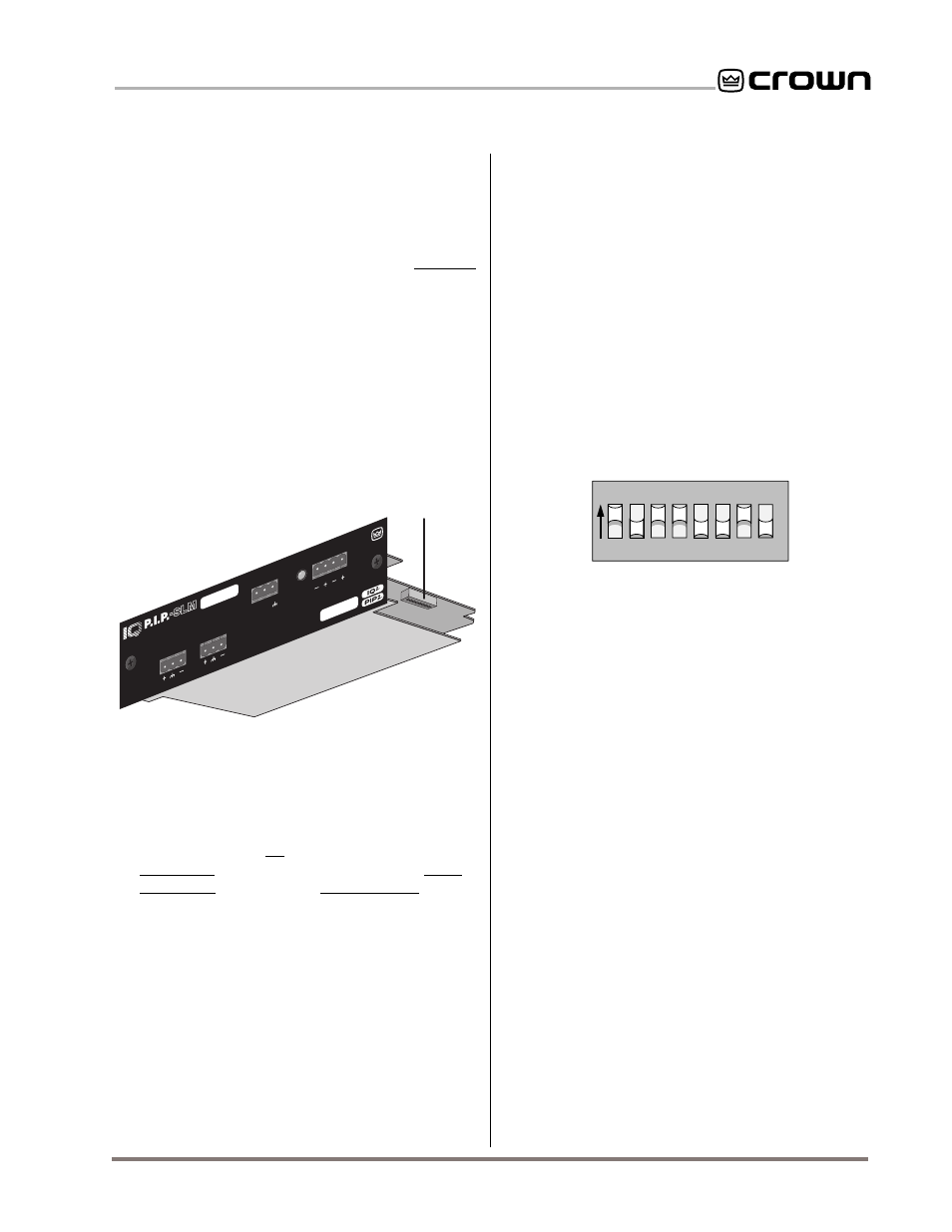
Switch SW1 is located on the right side on the
underside of the top circuit board (Figure 4.1). It
has eight segments because it actually contains
eight tiny switches inside. There is an arrow
printed on the switch along its left side that
points to the “ON” position and the switches are
numbered along the bottom (Figure 4.2).
BOTT
OM
OUT
IN
Programmable
Input Processor
AUDIO IN
CH-2
CH-1
AUX
OUT
IN
DATA
CROWN BUS
SLM#.###
SW1
Fig. 4.1 IQ Address Switch (SW1) Location
The 8-segment DIP switch (SW1) shown above
and in Figure 4.2 is used to set the IQ address of
the
IQ–P.I.P.–SLM. No two IQ components of the
same type which are connected to the same
Crown Bus can have the same address. Sup-
pose, for example, the
IQ System has two
Crown Bus loops and this
IQ–P.I.P.–SLM is in-
stalled into loop 1 and given address 77. No
other
IQ–P.I.P.–SLM can have the same address
in loop 1. However, an
IQ–P.I.P.–SLM in loop 2
can have the same address.
Different IQ components in the same Crown Bus
loop can have the same address. For example,
both an
SMX-6 mixer and an IQ–P.I.P.–SLM can
use address 77 in the same loop.
1
2
4
8
16
32
64
12
8
VALUE
TOP VIEW
1 2 3 4 5 6 7 8
ON
SW1
Fig. 4.2 IQ Address Switch (SW1) Values
Each of the eight switches in SW1 has a value
which doubles as the switch number increases.
For example switch 1 has a value of 1; switch 2
has a value of 2; switch 3 has a value of 4;
switch 4 has a value of 8 and so on.
The address is determined by adding the val-
ues of all switches which are turned on. In Fig-
ure 4.2 switches 1, 3, 4 and 7 are on. Simply add
the values to find the address: 1+4+8+64=77.
A convenient series of IQ address tables are in-
cluded in Section 7. The tables show the switch
settings for all 250 addresses. A diagram illus-
trating the IQ address switch values is also
printed on the right side of the bottom circuit
board for easy reference.
4.2 Prepare the Amplifier
2. Turn down the level controls
(full counter-
clockwise) and
turn off the amplifier.
3. Disconnect the amplifier’s power cord.
4. Remove the existing
P.I.P.
or cover panel from
the amplifier back panel (two screws). If the
amp is a PIP2 amplifier, it may contain a P.I.P.