Iq–p.i.p.–slm, 3 install the, Into the amplifier – Crown Audio IQ-P.I.P.-SLM User Manual
Page 16: 4 install the wiring
Page 16
IQ–P.I.P.–SLM Programmable Input Processor with Load Monitoring for IQ Systems
Reference Manual
card and a PIP2 input adapter. If so, remove
both the P.I.P. card and the PIP2 adapter by de-
taching the ribbon cables from the PIP2 adapter.
The P.I.P. card and PIP2 adapter may then be
inserted into another P.I.P.-compatible amplifier,
or may be stored for future use. Be sure to store
both the P.I.P. and adapter in antistatic packag-
ing.
4.3 Install the
IQ–P.I.P.–SLM
into the
Amplifier
5. Carefully ground yourself
to the chassis of the
amplifier before installing the
IQ–P.I.P.–SLM. It is
a good idea to maintain ground contact be-
tween yourself and the amplifier while inserting
the module into the
P.I.P.
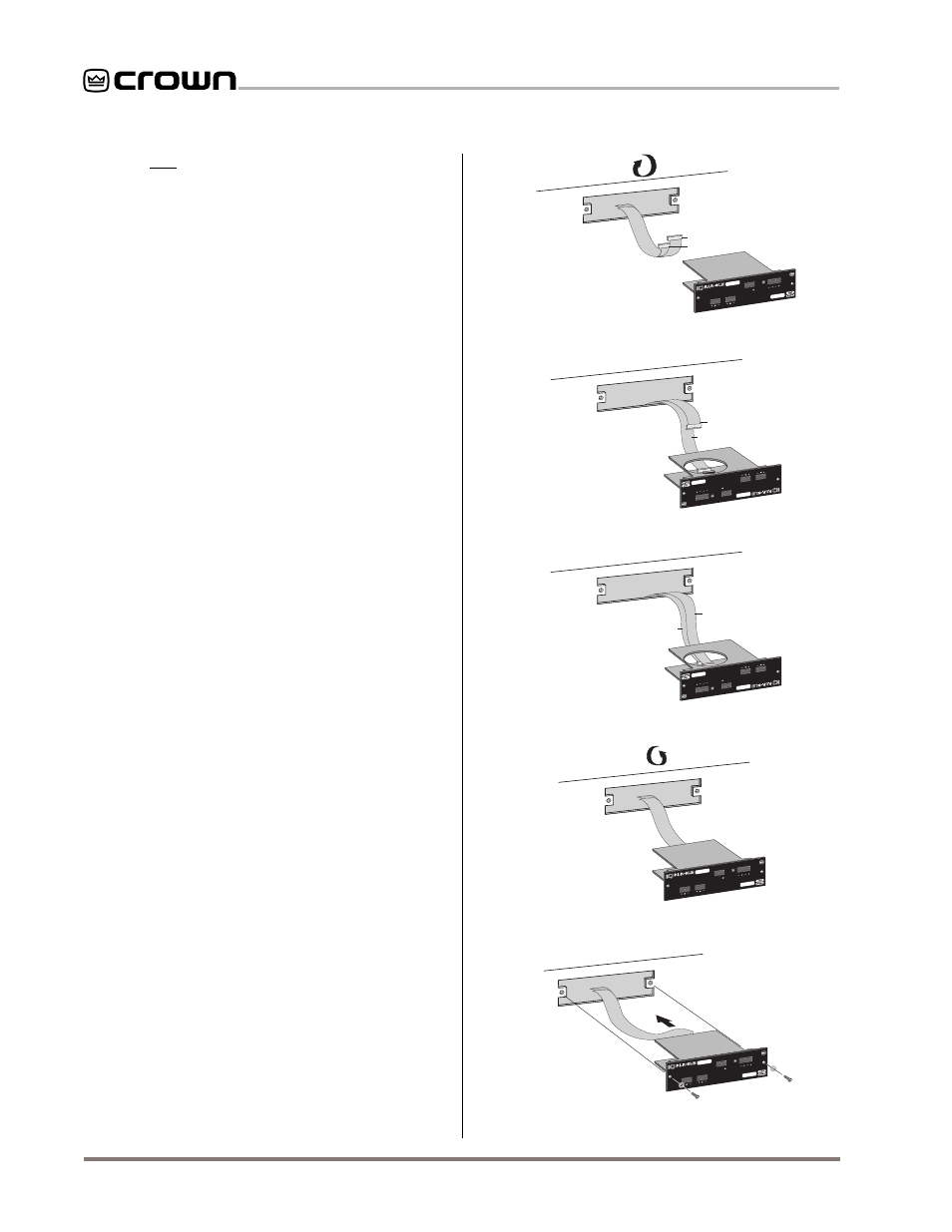
6. Install the
IQ–P.I.P.–SLM into the amplifier:
Turn the
IQ–P.I.P.–SLM over so that you can
clearly see the two ribbon-cable connectors lo-
cated on the underside of the top board near the
back corner (see Figure 2.1). Connect the two
input ribbon cables of the amplifier. The 20-pin
cable (A) should be connected first, then the 18-
pin cable (B) should be connected. Both ribbon
cables should run untwisted from the amplifier
to the
P.I.P. card (see Figure 4.3).
Impor
Impor
Impor
Impor
Important:
tant:
tant:
tant:
tant: Be careful when attaching the rib-
bon cable to the connector that the cable is
properly seated before applying pressure to the
connector. Forcing the cable onto the connector
could cause the keying tabs, which ensure
proper pin alignment, to break. Connecting the
ribbon cables with improper pin alignments may
well result in catastrophic damage to the P.I.P.
component.
When both cables are firmly attached, turn the
IQ–P.I.P.–SLM back to an upright position and
insert into the
P.I.P. opening in the back of the
amplifier. Take care while inserting the
P.I.P. to
make sure you do not crimp, pinch or stretch the
ribbon cables.
7. Tighten the two
P.I.P. mounting screws
until the
P.I.P. is secured to the amplifier back panel.
4.4 Install the Wiring
8. Connect the
IQ–P.I.P.–SLM to the IQ System
via the Crown Bus.
See Section 4.7 for full in-
structions.
Fig. 4.3 Installing the IQ–P.I.P.–SLM
OUT
IN
Programmable
Input Processor
AUDIO IN
CH-2
CH-1
AUX
OUT IN
DATA
CROWN BUS
SLM#.###
Rotate PIP2 180° in
opposite direction
BACK PANEL
OF PIP2
AMPLIFIER
OUT
IN
Programmable
Input Processor
AUDIO IN
CH-2
CH-1
AUX
OUT IN
DATA
CROWN BUS
SLM#.###
Slide PIP2 Into Amplifier
BACK PANEL
OF PIP2
AMPLIFIER
Plug In CABLE A
B
A
BACK PANEL
OF PIP2
AMPLIFIER
18 PIN (B)
20 PIN (A)
OUT
IN
Programmable
Input Processor
AUDIO IN
CH-2
CH-1
AUX
OUTIN
DATA
CROWN BUS
SLM#.###
BACK PANEL
OF PIP2
AMPLIFIER
18 PIN (B)
B
A
20 PIN (A)
OUT
IN
Programmable
Input Processor
AUDIO IN
CH-2
CH-1
AUX
OUT IN
DATA
CROWN BUS
SLM#.###
Rotate PIP2 180°
18 PIN (B)
20 PIN (A)
Plug In CABLE B
B
A
BACK PANEL
OF PIP2
AMPLIFIER
OUT
IN
Programmable
Input Processor
AUDIO IN
CH-2
CH-1
AUX
OUTIN
DATA
CROWN BUS
SLM#.###