Crown Audio IQ-P.I.P.-SLM User Manual
Page 18
Page 18
IQ–P.I.P.–SLM Programmable Input Processor with Load Monitoring for IQ Systems
Reference Manual
commands and data. As implemented in the
IQ–P.I.P.–
SLM, it is a 20 milliamp current loop operating at a
BAUD rate of 38.4 K. The loop must be unbroken.
If the system includes an
IQ–INT II interface, it can ac-
cept eight different Crown Bus loops or zones. Divid-
ing the sound system into different zones, each with its
own Crown Bus loop, can have several advantages.
The following list contrasts those advantages with
those of a single loop.
Multiloop Advantages
• A break in communication in one loop does not
affect other loops.
• Over 250 IQ components of the same type can
be used in a system.
• The same IQ address can be used more than
once (once per loop per model).
Single Loop Advantages (with IQ-INT II interfaces)
• The
IQ System can send and retrieve data faster
in a single loop.
• “Real time” level display of a greater number of
units is possible.
The
IQ–P.I.P.–SLM can be connected to the Crown Bus
with inexpensive twisted-pair wiring (shielded or un-
shielded). If fiber optic wiring is required, contact the
Crown Technical Support Group (see page 4).
Here are some guidelines for twisted-pair wiring:
• Use unshielded twisted-pair wir
Use unshielded twisted-pair wir
Use unshielded twisted-pair wir
Use unshielded twisted-pair wir
Use unshielded twisted-pair wire
e
e
e
e in most
cases, since unshielded wire has lower capaci-
tance and, typically, interference is not a prob-
lem. However, when interference is a problem,
you should use shielded twisted-pair wiring at
least 26 AWG in size. The wire should be of
good quality and should have low capaci-
tance—30 picofarads/foot or less is good. (West
Penn 452 or an equivalent wire works well.) The
shield serves two purposes: First, it helps pre-
vent the IQ data signal from transmitting to
nearby audio wiring. Second, it helps prevent
outside RF from interfering with the data signal.
•
Minimize the total capacitance of each
Minimize the total capacitance of each
Minimize the total capacitance of each
Minimize the total capacitance of each
Minimize the total capacitance of each
Cr
Cr
Cr
Cr
Crown Bus loop.
own Bus loop.
own Bus loop.
own Bus loop.
own Bus loop. The total capacitance should
be less than 30 nanofarads. Allow for approxi-
mately 60 picofarads for each IQ component in
a loop. This accounts for a slight delay which
occurs as data signals pass through a compo-
nent.
• Add an IQ Repeater
Add an IQ Repeater
Add an IQ Repeater
Add an IQ Repeater
Add an IQ Repeater for very long loops—
greater than 1,000 feet (305 m)—or when re-
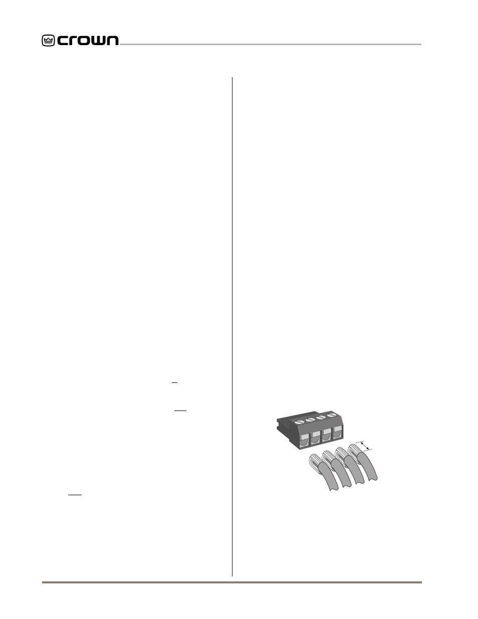
3/16 in
(0.48 cm)
Fig. 4.4 A Removable, Eurostyle Mating Plug
quired by high-capacitance wire. Although we
recommend a repeater for loops longer than
1,000 feet, it is often possible to go 2,000 feet
(610 m) or more. The most significant character-
istic of the wire is its capacitance. Lower capaci-
tance allows longer loops. Unshielded wire
usually has less capacitance.
• Never use the gr
Never use the gr
Never use the gr
Never use the gr
Never use the ground wir
ound wir
ound wir
ound wir
ound wire in a mic snake
e in a mic snake
e in a mic snake
e in a mic snake
e in a mic snake
line.
line.
line.
line.
line. It may sometimes be convenient to run
Crown Bus data signals to and from stage moni-
tor amplifiers along unused wire pairs in a mic
snake. Do not use the ground wire which is nor-
mally connected to pin 1 on an XLR connector
or data noise will be added to the audio lines.
Use only the signal lines which normally con-
nect to pins 2 and 3 of the XLRs.
Note: Because
typical mic cables have high capacitance, the
maximum possible Crown Bus loop distance will
be less.
Outside RF interference is seldom a problem for a
Crown Bus loop—especially if shielded twisted-pair
wire is used. However, there are extreme situations
when fiber optic wiring is recommended. For example,
locating a Crown Bus loop next to an AM radio trans-
mission line may require fiber optic cabling. An ex-
tremely long Crown Bus loop distance may also require
fiber optic cabling.
There are two different types of connectors used for
Crown Bus wiring: DIN connectors and removable
Eurostyle barrier block connectors. The
IQ–P.I.P.–SLM
uses a single 4-pin Eurostyle barrier block connector
that accepts a removable mating plug like the one
shown in Figure 4.4.
For reliable connection, cleanly strip the jacket from the
wire, twist and fold conductor back over the jacket. In-
sert wire into Eurostyle connector and tighten the set
screw.