G. aux input/output connector, H. signal generator, I. loudspeaker monitor output – Crown Audio IQ-SLM8 User Manual
Page 9: J. audio input/output connectors, Increments from 1 octave to
Page 9
IQ–SLM-8 System and Load Monitoring IQ System Component
Reference Manual
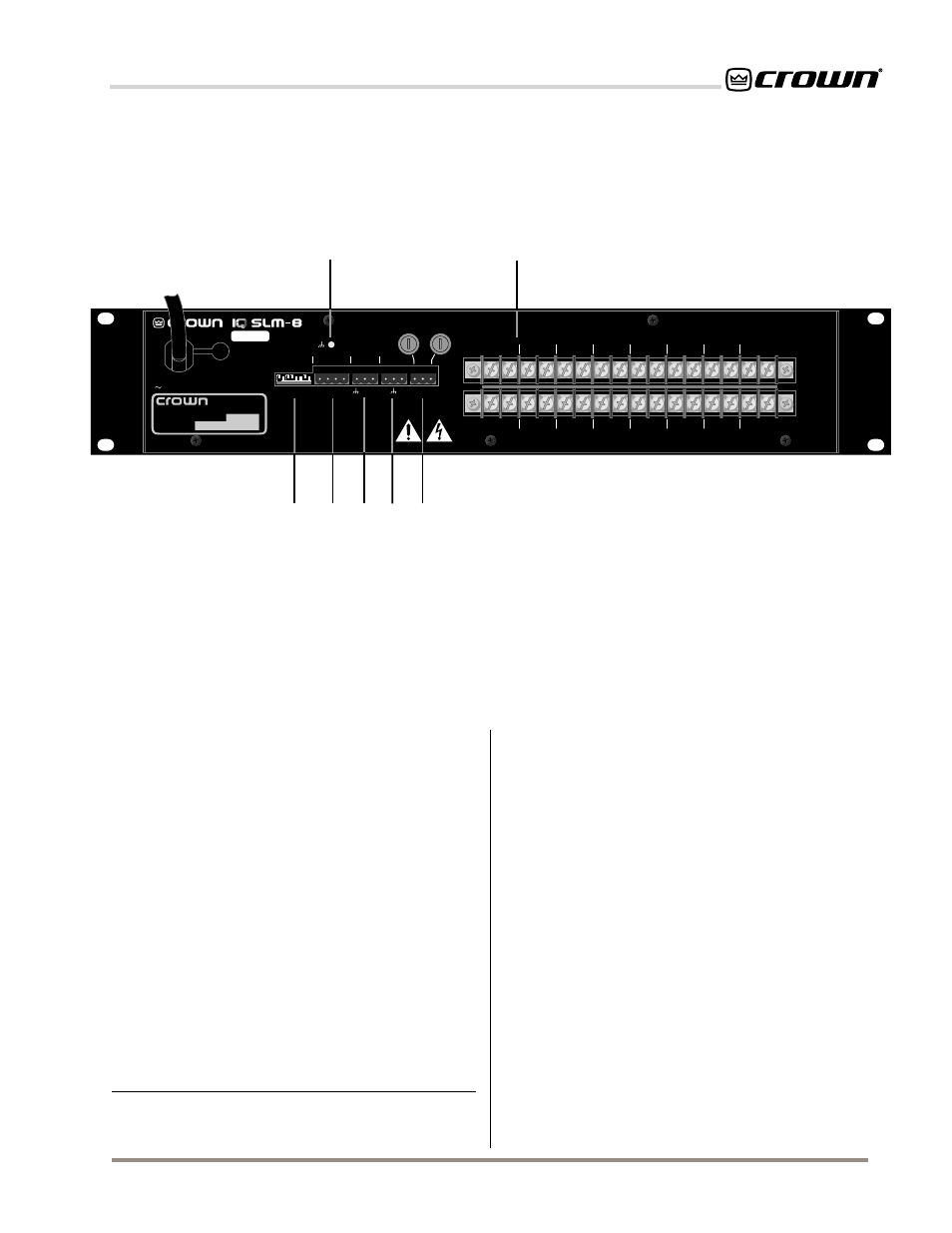
G. AUX Input/Output Connector
A 3-pin male “Euro-style” connector which accepts a
screw terminal plug is used for input and output con-
nection. The AUX output delivers 15 VDC at 15 mA
maximum output when switched on and may be con-
trolled via software or may be programmed to switch
when a fail condition is present on any channel.
1
The
AUX input has a high-impedance (10 kohm) and can
be programmed to trigger a test when a control volt-
age (logic high) is present. In this case, the sweep is
leading-edge triggered and may be aborted during a
test by sending a second leading-edge trigger.
H. Signal Generator
A 3-pin male “Euro-style” connector which accepts a
screw terminal plug is used for connection to the sig-
nal generator. This processor-controlled digital signal
generator provides a sine-wave output with variable
frequency from 20 Hz to 22 kHz and is selectable in
1
The AUX output uses inverse logic when it is configured to report a fail
condition. Normally high, it switches low when any channel fails a test. In
this way it can also indicate a power loss.
increments from 1 octave to
1
¤
24
octave. The generator
output level (amplitude) range is –40 dBu to +10 dBu
in 1 dB steps via a digitally controlled attenuator. Nor-
mally, the generator provides the swept sine wave
signal that is required for an impedance/frequency
test. The duration of a sweep will be determined by the
sweep resolution setting and the number of channels
being tested. The generator can also be turned on
manually with IQ software to provide a steady sine
wave output (test tone) at a fixed frequency.
I. Loudspeaker Monitor Output
A fused, 3-pin male “Euro-style” connector which ac-
cepts a screw terminal plug provides a relay contact to
any of the audio inputs (J). The relay is a break-before-
make type to prevent two channels from being mo-
mentarily shorted together.
J. Audio Input/Output Connectors
Sixteen pairs of screw terminals are provided for input
and output connection to the
SLM-8. Heavy-duty ter-
minals are provided to handle high-level wiring such
as loudspeaker cables.
+
–
1
+
–
2
+
–
3
+
–
4
+
–
5
+
–
6
+
–
7
+
–
8
+
–
1
+
–
2
+
–
3
+
–
4
+
–
5
+
–
6
+
–
7
+
–
8
INPUT
OUTPUT
IQ ADDRESS
INPUTS (FROM AMPLIFIER OUTPUTS)
OUTPUTS (TO LOUDSPEAKER INPUTS)
CROWN BUS
AUX
SIGNAL
GENERATOR
LOUDSPEAKER
MONITOR OUTPUT
FUSES*
*USE ONLY 1 A
SLOW-BLOW FUSES
+ – + –
+
–
+
–
IN OUT
IN
OUT
AC VOLTS: 100-120 AMPS: .25 50-60 Hz
AC VOLTS: 220-240 AMPS: .125 50-60 Hz
1
2
4
8
16
32
64
12
8
OFF
ON
CHASSIS
GROUND
®
INTERNATIONAL, INC.
ELECTRONIC EQUIPMENT
ELKHART, IN 46517
MADE IN U.S.A.
SERIAL NUMBER
0000
000000
SLMV#.###
1
2
3
4
5 6
7
8
J
E
D
F
G
H
I
Fig. 2.2 The Rear Facilities