8 using the aux connector – Crown Audio IQ-SLM8 User Manual
Page 17
Page 17
IQ–SLM-8 System and Load Monitoring IQ System Component
Reference Manual
logic high. A signal less than +1.6 VDC or an electrical
open will be interpreted as a logic “low.” See the IQ
software
User Manual for instructions on configuring
the
SLM-8 to respond to the AUX input.
Note: A negative signal can also be used as a logic
low because the signal is internally clamped to protect
the internal circuitry.
4.8.2 Signaling a Failed Test (AUX Output)
When the AUX output is turned on, +15 VDC is sup-
plied across pins 1 (ground) and 3 (+). A total of 15
milliamps of current is available. A 1.5 kohm resistor
protects against shorts.
The
SLM-8 can be configured by the IQ software to
signal a failed test via the AUX output. It does this with
reverse logic. The AUX port will be turned on to indi-
cate that all channels have passed the most recent
test and turned off to indicate that one or more chan-
nels have failed a test. By reversing the logic, the AUX
output will not send a pass signal when the unit it
turned off or has no power.
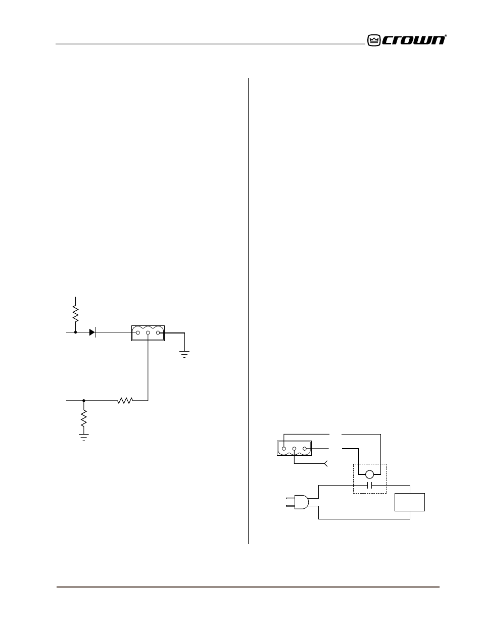
4.8.3 Controlling External Devices (AUX Output)
There are many other possible uses for the AUX out-
put. For example, it can be used to turn on auxiliary
cooling fans. To do this the +15 VDC AUX output would
be used to close a relay. The relay would then turn the
fans on or off. This principal is illustrated in Figure 4.16
below:
Note: A Crown part number is provided in Figure 4.16
for a suitable solid-state relay (C 8063-3). Contact your
local Crown representative or the Crown factory Parts
Department (219-294-8200) to order.
off the monitor outputs of all
SLM-8s in the IQ System
before it selects the desired channel. In this way mul-
tiple
SLM-8s can be connected to the same monitor
loudspeaker.
4.8 Using the AUX Connector
The AUX port can be used simultaneously for input
and output. For example, the AUX input can be used to
trigger a test and the AUX output can be used to signal
that one or more channels have failed an impedance
and/or frequency response test. Both of these features
must be configured from an
IQ System.
The AUX port can also function like a traditional IQ
AUX port. For example, the AUX output can be used to
switch a relay that can turn on/off other non-IQ compo-
nents in the system.
The internal AUX circuit is shown in Figure 4.15:
To comply with FCC regulations, an EMI suppression
core should be added (Section 4.9).
Fig. 4.15 The Internal AUX Circuit
AUX
CONNECTOR
INTERNAL AUXILIARY
CIRCUITRY
OUT
1.5 K ohm
+15 V
IN
20 K ohm
20 K ohm
GND
4.8.1 Triggering a Test (AUX Input)
The AUX input is a high impedance (10 kohm) input. To
trigger a test with it you must do two things: 1) Use IQ
software to set the
SLM-8 to respond to a logic “high”
at the AUX input; and 2) Connect an external voltage
(TTL level) to the AUX input across pins 1 (ground) and
2 (+). A +5 to +15 VDC signal will be recognized as a
AUX
CONNECTOR
GND
+15 V
AUXILIARY
EQUIPMENT
110 VAC
SOLID
STATE
RELAY
(C 8063-3)
+
–
INPUT
Fig. 4.16 A Sample AUX Output Circuit