4 installation, Slm-8, 1 prepare the – Crown Audio IQ-SLM8 User Manual
Page 12: 2 mounting, Iq address switch, Fig. 4.3 mounting dimensions
Page 12
IQ–SLM-8 System and Load Monitoring IQ System Component
Reference Manual
4 Installation
The installation of an
SLM-8 consists of two major
parts: installing the hardware and configuring the unit
with IQ software. This manual deals with hardware
installation. Please refer to an appropriate IQ software
User Manual for software instructions.
4.1 Prepare the
SLM-8
Step 1: Set the IQ address switch.
By giving each IQ
component a unique address, it can be individually
controlled and monitored. Whenever the
IQ System
wants to send a command to just one IQ component, it
first sends its address and then the command down
the Crown Bus.
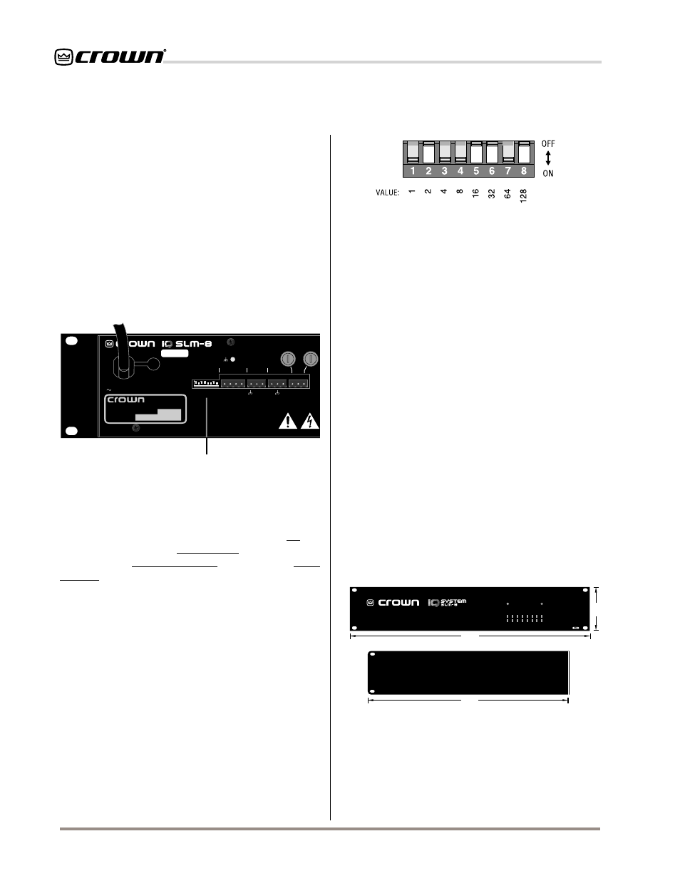
Fig. 4.1 IQ Address Switch Location
Fig. 4.2 IQ Address Switch Values
Each of the eight segments has a value which doubles
as the segment number increases. For example, seg-
ment 1 has a value of 1; segment 2 has a value of 2;
segment 3 has a value of 4; segment 4 has a value of
8; and so on.
The address is determined by adding the values of all
“ON” segments. In Figure 4.2 switches 1, 3, 4 and 7
are on. Simply add the values to find the address:
1+4+8+64=77.
A convenient series of IQ address tables are included
in Section 7. The tables show the settings for all 250
addresses.
4.2 Mounting
Step 2: Mount the unit.
The
SLM-8 is designed to be
mounted in a standard 19-inch (48.3-cm) equipment
rack or cabinet. Only two vertical rack spaces are
required and its 16-inch (40.6-cm) depth matches the
depth of most Crown amplifiers, making it easier to
wire. It can also be “stack” mounted outside of a
cabinet. The mounting dimensions are shown below in
Figure 4.3:
The 8-segment DIP switch shown in Figures 4.1 and
4.2 is used to set the IQ address of the
SLM-8. No two
IQ components of the same model which are con-
nected to the same Crown Bus can have the same
address. Suppose, for example, an
IQ System has two
Crown Bus loops, and this
SLM-8 is to be installed into
Loop 1 and given an address of 77. No other
SLM-8
can be given the same address in Loop 1. However,
an
SLM-8 in Loop 2 can have the same address.
Different IQ components in the same Crown Bus loop
can have the same address. For example, both an
AMB-5 mixer and an SLM-8 can use address 77 in the
same loop.
A valid IQ address is any number from 1 to 250. Do not
use a number higher than 250 since they are reserved
for special use.
The IQ address switch is located on the back panel of
the unit (Figure 4.1). It has eight segments because it
actually contains eight tiny switches inside. Flipping
them down, turns them on and flipping them up turns
them off.
IQ ADDRESS
CROWN BUS
AUX
SIGNAL
GENERATOR
LOUDSPEAKER
MONITOR OUTPUT
FUSES*
*U
S
+ – + –
+
–
+
–
IN OUT
IN
OUT
AC VOLTS: 100-120 AMPS: .25 50-60 Hz
AC VOLTS: 220-240 AMPS: .125 50-60 Hz
1
2
4
8
16
32
64
12
8
OFF
ON
CHASSIS
GROUND
®
INTERNATIONAL, INC.
ELECTRONIC EQUIPMENT
ELKHART, IN 46517
MADE IN U.S.A.
SERIAL NUMBER
0000
000000
SLMV#.###
1
2
3
4
5 6
7
8
IQ Address Switch
19 in
48.3 cm
16 in
40.6 cm
3.5 in
8.9 cm
SIDE VIEW
POWER
DATA
1
2
3
4
5
6
7
8
PASS / FAIL INDICATORS
PASS: GREEN / FAIL: RED
IMPEDANCE RESPONSE
FREQUENCY RESPONSE
Fig. 4.3 Mounting Dimensions