2 facilities, A. data indicator, B. pass/fail indicators – Crown Audio IQ-SLM8 User Manual
Page 8: C. power indicator, D. iq address switch, E. crown bus ground connector, F. crown bus input/output connector
Page 8
IQ–SLM-8 System and Load Monitoring IQ System Component
Reference Manual
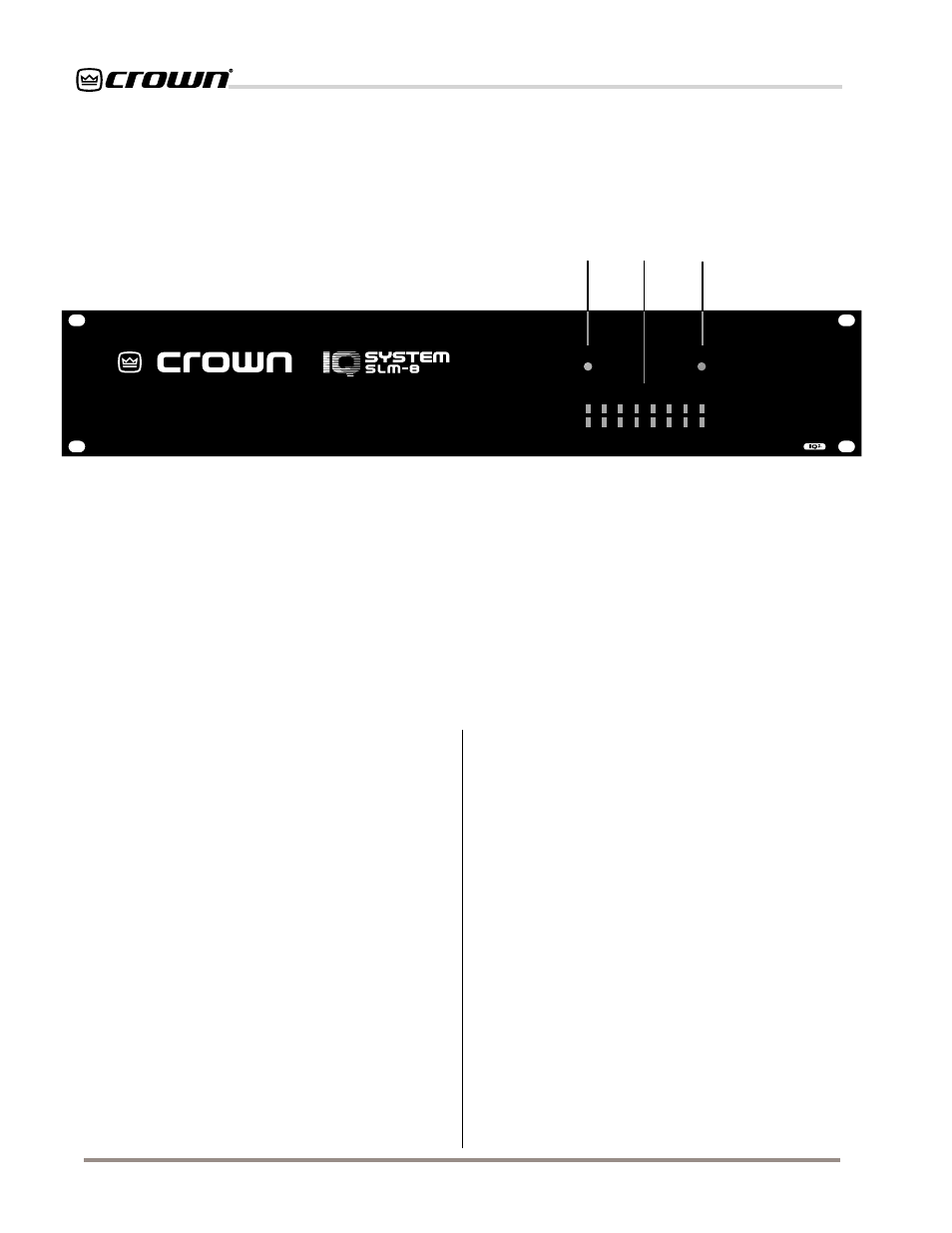
Fig. 2.1 The Front Facilities
2 Facilities
A. Data Indicator
The Data LED flashes yellow when the unit is actively
communicating (transmitting data) via the Crown Bus.
It may also be forced to stay on by IQ software.
B. Pass/Fail Indicators
Two rows of eight two-color LEDs light solid green/red
to indicate pass/fail status for each monitor channel
within the unit. LEDs in the upper row indicate imped-
ance response test status; LEDs in lower row indicate
frequency response test status. Alternate red/green
flashing indicates that testing is in progress.
C. Power Indicator
The Power LED lights amber to indicate the presence
of AC mains power.
D. IQ Address Switch
An 8-section DIP switch is used to set the IQ address
of the unit. It must have a unique IQ address so it can
be independently controlled and monitored by the sys-
tem. Two or more IQ components of the same type
should NEVER have the same address on the same
Crown Bus loop (See Section 4.1).
Important: The IQ
address should only be set with the power cord
disconnected from the AC supply.
E. Crown Bus Ground Connector
A chassis ground stud is provided to connect an op-
tional shield for the Crown Bus cable. Only the shield of
the input cable should be connected. Shielded wire
may reduce the total distance a Crown Bus loop can
be run (because shielded wire usually has higher ca-
pacitance), but shielding may be necessary to reduce
interference with certain types of audio cables. (See
Sections 4.3 and 4.6)
F. Crown Bus Input/Output Connector
A 4-pin male “Euro-style” connector which accepts a
screw terminal plug is used for input and output con-
nection to the Crown Bus.
The pins are numbered
from right to left (as you face the back panel of the
unit).
Pin 1 is input negative (–), and pin 4 is output
positive (+). (See Sections 4.3 and 4.6)
POWER
DATA
1
2
3
4
5
6
7
8
PASS / FAIL INDICATORS
PASS: GREEN / FAIL: RED
IMPEDANCE RESPONSE
FREQUENCY RESPONSE
C
B
A