1 welcome, 1 unpacking – Crown Audio IQ-SLM8 User Manual
Page 7
Page 7
IQ–SLM-8 System and Load Monitoring IQ System Component
Reference Manual
1 Welcome
The
IQ–SLM-8 System and Load Monitor is a versatile
eight-channel monitoring device with a built-in test sig-
nal generator. It can monitor the impedance response
1
of eight different loads (such as loudspeakers) and/or
the frequency response
2
of eight line-level or high-level
outputs. When a load or output is tested, the unit will
compare the results to a reference measurement
stored inside its memory and display either a pass or
fail signal with its two-color indicators on the front
panel. The unit also sends pass/fail information to an
IQ System if one is connected. The pass/fail tolerance
of each channel is set individually.
The
IQ–SLM-8 (we’ll shorten the name to SLM-8 for the
rest of this manual) can serve as a valuable trouble-
shooting tool to help you identify problems before they
become severe. For example, with an impedance test,
you may be able to locate a damaged loudspeaker
before it fails completely. In addition, the
SLM-8 can
serve as a powerful security tool to help you prevent
unauthorized changes to an audio system. For ex-
ample, you can monitor the frequency response of an
output to verify that both level and equalization settings
have not been changed.
The
SLM-8 is also an IQ2-compatible component. This
means it can be both monitored and controlled by a
Crown
IQ System. However, with its front-panel pass/
fail indicators and its ability to initiate a test with an
external switch, it can also be used in a stand-alone
mode after it has been configured by an
IQ System (a
host computer running appropriate IQ software and an
IQ interface is required for setup).
This manual will help you successfully install your unit.
Please read all the instructions, warnings and cautions
contained within it. Also, for your protection, please
send in the warranty registration card today. And save
the bill of sale—it is your official proof of purchase.
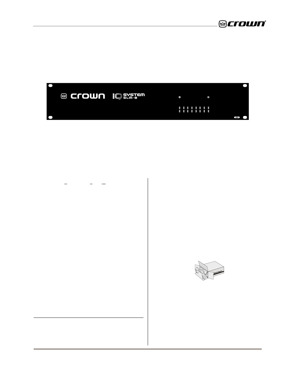
Fig. 1.1 The IQ–SLM-8
POWER
DATA
1
2
3
4
5
6
7
8
PASS / FAIL INDICATORS
PASS: GREEN / FAIL: RED
IMPEDANCE RESPONSE
FREQUENCY RESPONSE
1.1 Unpacking
Please inspect the unit for any damage that may have
occurred during transit. If damage is found, notify the
transportation company immediately. Only you, the
consignee, may initiate a claim with the carrier for
shipping damage. Crown will cooperate fully as
needed. Save the shipping carton as evidence of
damage for the shipper’s inspection.
Please save all packing materials.
NEVER SHIP THE
UNIT WITHOUT THE FACTORY PACK.
1
The term “impedance response” is used to refer to the impedance
magnitude of a load. It is calculated by measuring the current that flows
to the load and the voltage across the load verses frequency.
2
The term “frequency response” is used to refer to the amplitude
response or voltage magnitude of an output. It is calculated by measur-
ing the voltage across an output verses frequency.