Front panel features, Back panel features – Crown Audio I-Tech HD Series User Manual
Page 8
I-Tech HD Series
Power Amplifiers
I-Tech HD Series
Power Amplifiers
page 14
page 15
Operation Manual
Operation Manual
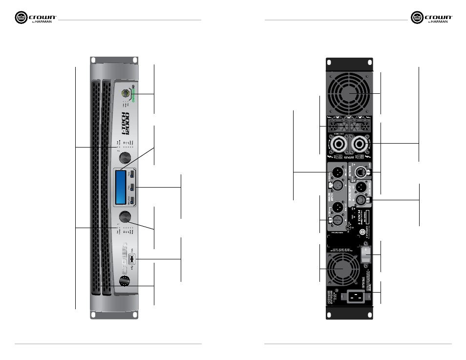
Front Panel Features
Gain (Level) Controls:
Two black rotar
y level controls,
one for each channel.
Cooling V
ents:
Front-to-rear forced airflo
w
through foam dust filter
.
Sel/Prev/Ne
xt Buttons:
Three buttons loca
ted
undernea
th the LCD screen
used to access menu items
and front panel lockout.
USB 2.0 Connector:
Accepts a USB drive to transfer
presets from the drive to the
amplifier DSP
, and vice versa.
Power Button & Indicator:
Push-on/push-off s
witch glo
ws
green when
AC po
wer is present a
t
the po
wer cord and the amplifier
circuit breaker is in the
“on”
position.
LCD Screen:
Backlit liquid cr
ystal display
sho
ws enabled presets and
speaker processing.
Ind
ic
at
or
s:
Fa
ul
t I
ndi
ca
to
r:
Re
d L
ED
, o
ne p
er c
ha
nn
el
, fl
as
he
s w
he
n t
he a
m
pli
fie
r o
ut
pu
t c
ha
nn
el h
as s
to
pp
ed o
pe
ra
tin
g. U
su
all
y t
hi
s m
ea
ns t
ha
t t
he a
m
pli
fie
r m
us
t b
e s
er
vi
ce
d.
Th
erm
al
In
di
ca
to
r:
Re
d L
ED
, o
ne p
er c
ha
nn
el
, ill
um
in
at
es w
he
n t
he c
ha
nn
el h
as s
hu
t d
ow
n d
ue t
o t
he
rm
al s
tr
es
s o
r o
ve
rlo
ad
.
Cl
ip I
nd
ic
at
or
: R
ed L
ED
, o
ne p
er c
ha
nn
el
, ill
um
in
at
es w
he
nt t
he c
ha
nn
el
’s o
ut
pu
t s
ig
na
l r
ea
ch
es t
he o
ns
et o
f a
ud
ib
le c
lip
pi
ng
. T
he C
lip i
nd
ic
at
or a
ls
o w
ill ill
um
in
at
e
du
rin
g T
he
rm
al L
eve
l C
on
tr
ol (
TL
C) li
m
iti
ng
. T
he C
lip I
nd
ic
at
or c
an b
e t
ur
ne
d o
f d
ur
in
g B
la
ck
ou
t m
od
e.
-1
0 d
B I
nd
ic
at
or
: a
m
pli
fie
r o
ut
pu
t i
s 1
0 d
B b
el
ow c
lip
pi
ng
.
-2
0 d
B I
nd
ic
at
or
: a
m
pli
fie
r o
ut
pu
t i
s 2
0 d
B b
el
ow c
lip
pi
ng
.
Si
gna
l I
ndi
ca
to
r:
s
el
ec
te
d i
np
ut s
ig
na
l i
s a
bo
uve -
40 d
Bu
.
Re
ady
In
di
ca
to
r:
Gr
ee
n L
ED
, o
ne p
er c
ha
nn
el
, ill
um
in
at
es w
he
n t
he c
ha
nn
el i
s i
ni
tia
lize
d a
nd r
ea
dy t
o p
ro
du
ce a
ud
io o
ut
pu
t. I
nd
ic
at
or i
s o
ff w
he
n t
he c
ha
nn
el i
s s
et
to s
ta
nd
by m
od
e v
ia S
ys
te
m A
rc
hi
te
ct o
r i
n B
la
ck
ou
t m
od
e.
Back Panel Features
Binding P
ost Output Jacks:
One pair per channel of high-current,
60A color
-coded binding posts.
Accepts
banana plugs,wire of spade lugs.
Fans:
Provide front to back
forced airflo
w for cooling.
AC P
ower
Connector
4-P
ole Speakon
®
Output Connectors:
These two connectors accept 2-pole or 4-pole Speakon
connectors.
The channel 1 connector is wired for both channels
so it can be used for bridge-mode wiring or stereo wiring of two
speakers to a single Speakon.
Network Connector:
This EtherCon
®
Ethernet
connector is for networking.
W
arning:
Only connect to
networks tha
t remain inside
the building.
Reset Switch/
Circuit Breaker
Balanced Analog
XLR Inputs:
Provide front to back
forced airflo
w for cooling.
Balanced Analog XLR Loop-Through Outputs:
Two 3-pin male XLR output connectors are provided (one per
channel).
The signal a
t these connectors is paralleled with the
Input signal for feeding the input signal to other amplifiers.
AES/EBU Digital Input:
This 3-pin female XLR
connector accepts a digital
signal in the
AES/EBU forma
t.
Fans:
Provide front to back forced
airflo
w for cooling.