3B Scientific Foucault Pendulum (230 V, 50__60 Hz) User Manual
Page 9
9
Excitation:
Electromagnetic pulse excitation mechanism
Integrated, photovoltaic cell for synchronisation
Switch for regulating the amplitude
Indicator lamp for excitation
Housing:
Glazed metal housing
with door:
40 cm x 40 cm x 150 cm
Stand base with 4
adjustable feet for
plumb vertical
positioning Lighting: Fluorescent tube 36 W,
50/60 Hz
Power supply:
115 V or 230 V, 50/60 Hz
Mains fuse:
0.063 A, slow blow
3. Operation
3.1 Setup
3.1.1 Assembly
∑ Set up Foucault's pendulum on a horizontal surface
with a stable foundation.
∑ Using your hands, check the housing and the ring for
vibrations. If any vibrations are felt, it means that
this place is unsuitable. If a floor is able to vibrate, a
spot must be chosen where few people are likely to
pass close by. Pay special attention to air conditio-
ning units and other appliances that are capable of
generating vibrations.
∑ Avoid direct solar radiation, as this may make it diffi-
cult to register the shadow projected from the string
and possibly even cause incorrect triggering of the
photovoltaic cell.
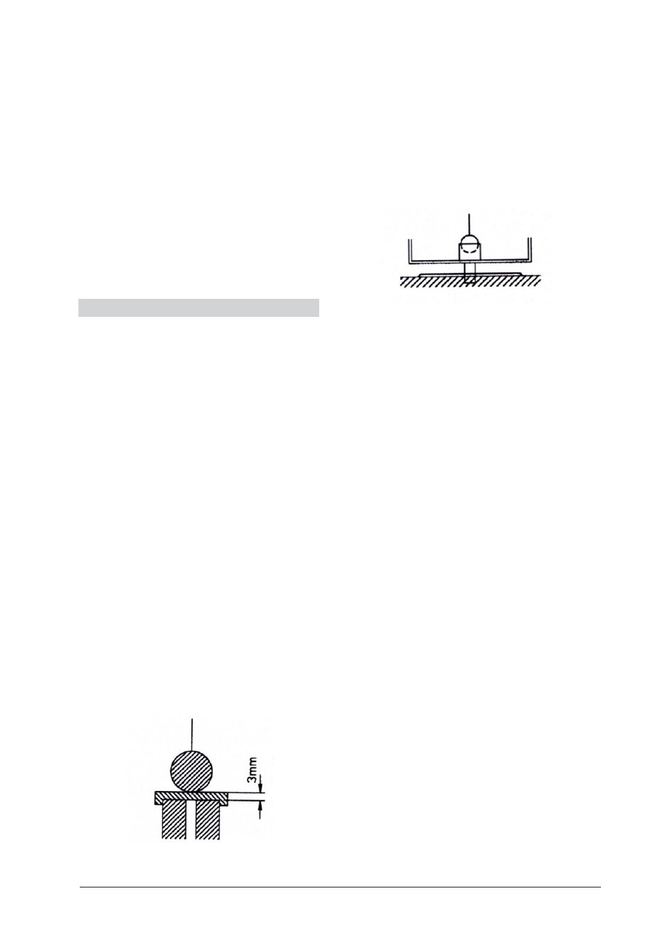
3.1.2 Mounting the pendulum
∑ Set the distance between the pendulum bob and the
electromagnet to approx. 3 mm. This distance is achie-
ved when the bob barely touches the plate that can
be laid over the electromagnet in order to make this
adjustment (see Fig. 7). If the distance is too great,
the effect of the excitation mechanism is weaker.
∑ If the bob is suspended for a longer period, then the
distance should be checked, because the string can
stretch by 1 to 2 mm.
Fig. 7: Distance between the pendulum bob and the electromagnet
3.1.3 Horizontal adjustment
∑ Insert the adjustment cylinder onto the measuring
scale and insert the pendulum bob into this cylinder
(see Fig. 8).
∑ For correct adjustment, turn the feet of the stand
base till a suitable height is attained. Adjustment be-
comes easier when two feet of the stand base are
moved simultaneously.
∑ The bob must be suspended exactly in the middle of
the cylinder.
Fig. 8: Horizontal adjustment
3.1.4 String projection
∑ After switching on the projection lamp, while retain-
ing the suspended bob in the adjustment cylinder,
make sure that the string projection covers the verti-
cal line on the screen.
∑ This factory calibration may need to be carried out
once again when the bulb has to be changed (see
3.3).
3.2 Experimental procedure
∑ Check whether all preparations described in 3.1 have
been carried out.
∑ If the experiment is to be carried out only with the
natural swing of the pendulum, then the switch for
excitation of the pendulum must be switched to
"OFF". In this case, the swing of the pendulum is
reduced to less than 1/3 of its
initial amplitude in
15 minutes. The measurements must be conducted
within this period.
∑ If the experiment is conducted with excitation, then
the amplitude must be observed for approx. 5 min-
utes and, if required, should be corrected using the
excitation adjustment switch.
∑ Displace the pendulum bob by hand and release it.
During the experiment, the pendulum must swing in
one and the same plane. If it begins to swing in an
elliptical path, the experiment will have to be stopped
and restarted.
∑ Shut the door carefully.
∑ When the swinging motion becomes stable after a
few minutes, set the protractor disc such that the
projected image of the string coincides with the base-
line.
∑ The measurement of the angle of rotation is con-
ducted at the point where the string projection on
the screen stops moving horizontally as the angle
adjustment dial is turned.
∑ If the string projection unit does not move while the
angular adjustment dial is rotating, then check wheth-
er the locking screw has been properly screwed down.