10 joint plate assembly, 1 joint plate assembly, top running end carriages – R&M Materials Handling WIRE ROPE PACKAGES User Manual
Page 50
R&M Materials Handling, Inc.
4501 Gateway Boulevard
Springfield, Ohio 45502
P.: (937) 328-5100
FAX: (937) 325-5319
50/76
R&M Materials Handling, Inc. reserves the right to alter or amend the above information without notice.
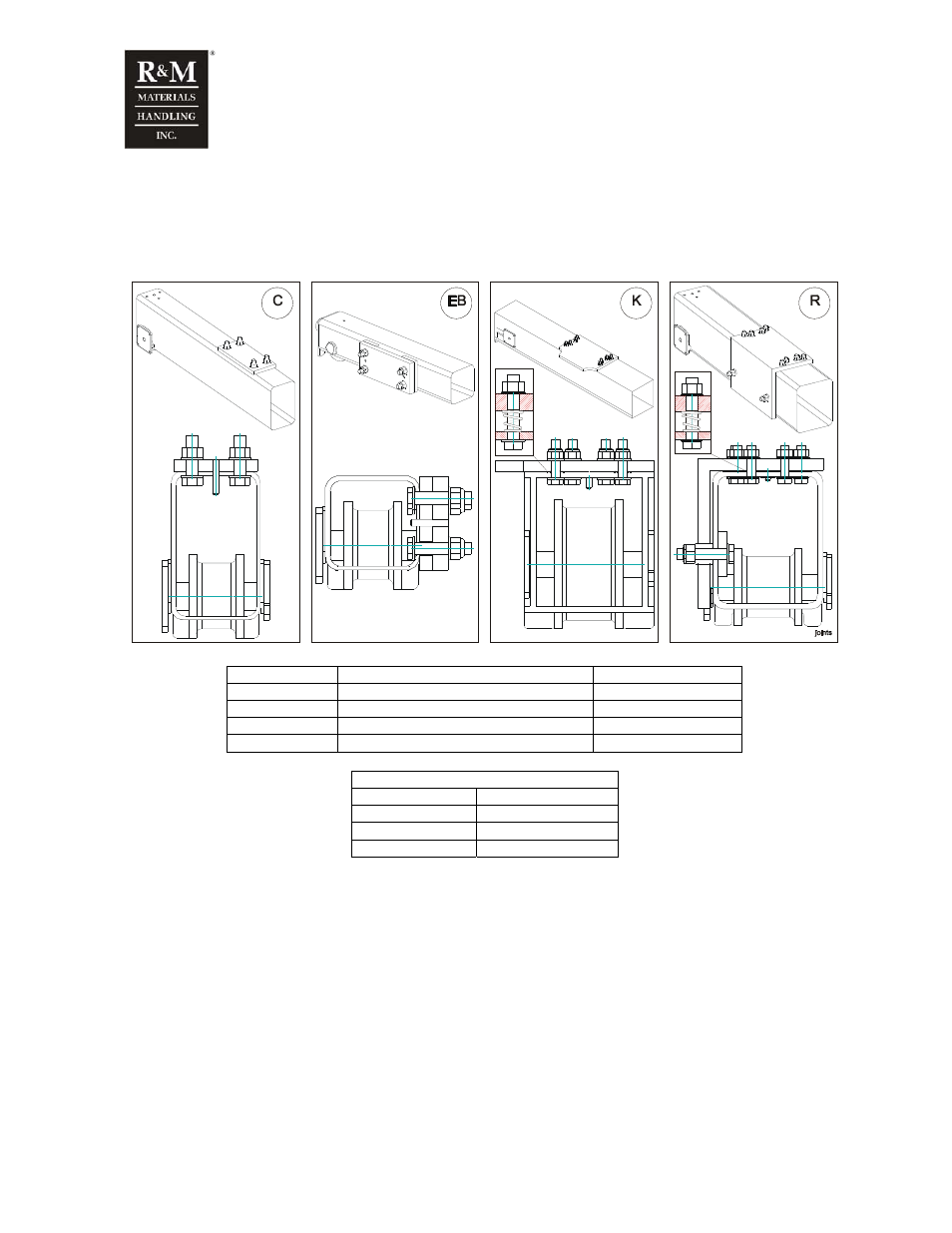
10 Joint plate assembly
10.1 Joint plate assembly, top running end carriages
Pos. Connection
Friction
rings
EB Side
connection
No
C, C-Gantry
Top connection
No
P, L, K
Top connection
Yes
R, S
Top connection / Side connection
Top yes, side no
Tightening torque
Screw size
Tightening torque
M16-10.9 280
Nm
M20-8.8 385
Nm
M20-10.9 550
Nm
• Check that joint surfaces are free from dirt, dust and loose particles. Only shop primer paint is
allowed.
• Place friction rings around screw holes at top of end carriage.
• Reset spring pins into the holes at joint plates so that pin head penetrates the plate about 10-20
mm below bottom surface.
• Place joint plate above the end carriage. Make sure, that spring pins contact with corresponding
holes at the end carriage top plate. Drive pins trough both plates with a hammer and proper tool.
Make sure, that friction rings are kept in position during assembly.
• Assemble screws and nuts.
• Assemble joint plate into final position and tighten screws with correct torque.
• Retighten screws after test runs at assembly site.