Newport Brass 2510-5203 User Manual
Page 2
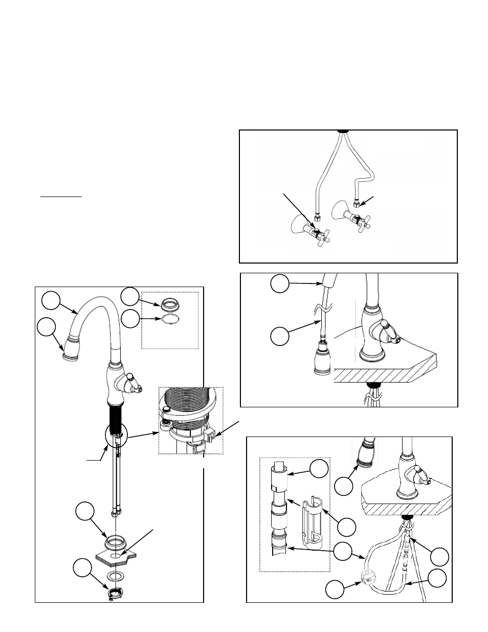
NWP-2510-5103
Figure 1
Figure 1a
1
3
2
Mounting
surface
hole
Recommended Installation by a Professional Plumbing Contractor
Note: The use of petroleum base plumbers putty on our products will nullify the warranty. We recom
mend the use of clear silicone sealing materials.
If mounting faucet to stainless steel rim, an under-mount support, (e.g. wood, appropriate size x 1/2”
thick), should be utilized.
1. Drill hole in mounting surface. Recommended deck hole Ø1.350”
not to exceed Ø1.562”.
2. Place O-ring (2) on underside of base RING (1). See Figure 1a.
3. Insert Hoses through base RING (1) and hole in
mounting surface. Secure into place with MOUNT-
ING KIT (3). See Figure 1.
4. Attach hot/cold spout supply directly to valves in
the wall. See Fig. 2
5. DO NOT remove the HOSE (6) from SPOUT (4).
See Figure 3.
6. Slide WEIGHT(9) onto HOSE(6). See Figure 4.
7. Connect HOSE (6) to valve outlet (8).
See Figure 4. Attach CLIP (7) to the connection
between HOSE (6) and OUTLET (8).
See Figure 4a.
REV A
Figure 2
Wall valves
(not included)
9/16-24 UNEF
(FOR 3/8” COMPRESSION
OUTLET )
1
4
5
Figure 3
6
4
DO NOT REMOVE
ZIP TIE
See Detail A
Detail A
3/8” COMPRESSION
OUTLET
Figure 4
7
8
8
6
9
5
Figure 4a
6