Newport Brass 7301 Newport 365 User Manual
Page 2
PLM-7301
Recommended Installation by a Professional Plumbing Contractor
Note: Use Teflon tape or equivalent to seal all threaded port joints.
Warning: To prevent severe damage to valve BODY (5), any solder/braze process must be performed a min. of 4” from ports and
it is important to REMOVE O-RING (6) FROM TAILPIECE (8) PRIOR TO APPLYING ANY HEAT/FLAME.
Note: The use of petroleum based plumber’s putty on our products will nullify the warranty.We recommend the use of clear silicone sealing
materials.
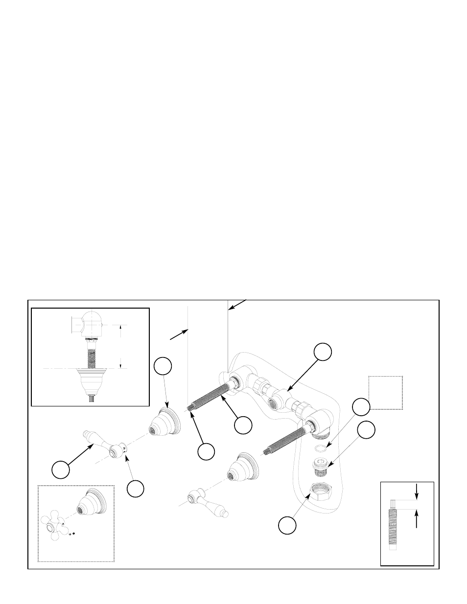
Valve Installation: (Reference Figure 1)
Turn off water to valve.
Slide union NUT (7) onto copper supply pipes and thread or solder/braze union TAILPIECE (8) onto copper
supply pipes.
Tighten union NUT (8) onto valve BODY (5). Check the level of valve BODY (5) assembly.
Turn on water supply, pressurize system and check for leaks.
Measuring and cutting stem length:
Remove ALL-THREAD (2) and indicate on STEM (1) a measured distance of 2-9/16” from finished wall surface.
Using a hacksaw, cut excess length of STEM (1) off. Trim an additional 3/4” of ALL- THREAD (2) length from
end of STEM (1). See Figure 1A.
Handles:
(All trim must be installed on finished wall surface)
Thread ESCUTCHEON (3) onto ALL-THREAD (2) and flush against finished wall. Place HANDLE (4) onto
STEM (1) and tighten SETSCREW (9). Allow a minimal space between HANDLE (4) and ESCUTCHEON (3).
Note: To achieve desired handle rotational alignment, the carthridge MUST be tightened in clockwise rota-
tion only. (Cartridge Bonnet factory torque of 14 ft-lbs. must be maintained.)
1/2” sweat connection
combo 1/2 NPT
Figure 1
2 9/16”
3/4”
3-5/16” MAX
1-5/16” MIN
Finished wall
1
2
3
4
5
8
7
Figure 1A
9
Cross handle
See
warning
above
6