B&B Electronics MESR424T_D-MT_D-SC - Quick Start Guide User Manual
Product overview, Set up network, Set up hardware
4
3
Set Up Network
1
Set Up Hardware
1. Power the device.
2. Connect the top RJ45 or optical connector
to a network drop using a standard network
cable. (The RJ45 ports on the model shown are
interchangeable. One may used for pass-through
Ethernet.)
3. Connect the Serial Device(s).
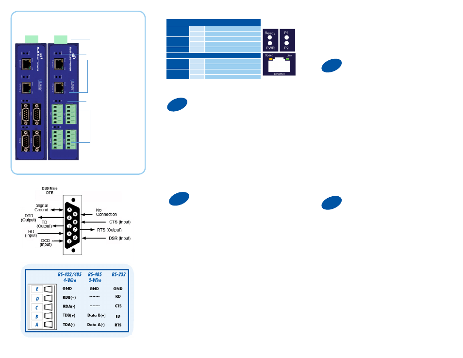
RS-232 with DB9: straight-through for DCE
device. Null modem for DTE device.
RS-422/485 with terminal blocks.
Product Overview
Power
10 - 48 VDC
If You Wish to Set Up TCP
1. Use included CD to install Vlinx Modbus Gateway
Manager. If Autorun does not start, go to “My
Computer” and select the CD drive. You will see
a Vlinx MESR icon. Double-click it to launch the
installation.
2. To open Vlinx Modbus Gateway Manager: click
Start\Programs\B&B Electronics\Vlinx\Vlinx Modbus
Gateway Manager.
If the device does not connect, cycle (unplug-replug)
the power, then try again.
3. To configure via the network, select “Network”.
4. If you know the IP address, select “The device is
at this address,” and type in the IP address. If not,
select “I don’t know the IP address of the device.” Click
Connect.
(Alternative Method: Open a web browser and type
the IP address of the Gateway in the Address Bar.
When the Gateway is found the Login window will
appear.)
2
Install/Setup
“I want DHCP” is preselected to set up the network
using dynamic IP addressing. The Gateway is set
up at the factory to receive an IP assignment from a
DHCP Server.
1. If a DHCP Server is not available on your network,
it will default to 169.254.102.39.
2. If a DHCP server is not available and the default
address does not work on your PC, change your PC
network settings to IP Address: 169.254.102.1, Subnet
Mask: 255.255.0.0, Default Gateway: 169.254.1.1.
If you are not able to use these settings in your
installation, refer to the User’s Manual for directions to
change the Gateway’s TCP/IP settings.
Note: The Vlinx Modbus Gateway Manager
software contains default parameter values that
are common to most Modbus networks.
TCP Settings:
“Connect to port” identifies TCP port used in TCP
client mode. Valid range is 1 to 65535. Default is
502.
Response timeout is the maximum response time.
Valid range is from 1 to 65535. Default is 100ms.
TCP Server Settings:
“Listen on port” identifies TCP port in TCP server
mode. Valid range is from 1 to 65535. Default is
502.
“Limit the number of connections” controls the number
of simultaneous TCP clients that can be connected.
Connection Filter Mode options like “allow everyone,”
“allow specific IP address” and “allow a range of IP
addresses” control which TCP clients can connect.
5. Click “Login”. Password is blank from factory.
No password is necessary to operate the MESR
unit. The Configuration/General page appears.
Fiber/Ethernet
Ports
Male DB9 Ports or
Terminal Block Ports
LEDs
LEDs
LEDs
Power
Off
Power is not connected
On
Power is connected
Ready
Off
System is in Console Mode
Blink
System is in Normal Mode
P (1 - 4)
Blink
Data present on serial port
RJ45 Ethernet Port LEDs
Speed
Off
10BaseT connection
On
100BaseTX connection
Link
On
Ethernet connected
Blink
Data present on Ethernet port