Arbitration field (y1, y2, y3, y4) – B&B Electronics HDV100A3 - Manual User Manual
Page 25
HDV100A3 Command & Response Manual
21
Cover Page
B&B Electronics -- 707 Dayton Rd. -- PO Box 1040 -- Ottawa, IL 61350
PH (815) 433-5100 -- FAX (815) 433-5104
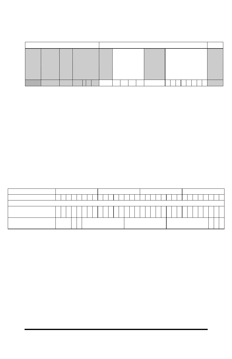
Data messages received from the HDV100A3 operating in the J1939 mode,
is formatted as follows:
Control Field
Data Field
Start
of
Frame
# of
Control
bytes
Contr
Byte
Time Stamp
4 Bytes
# of
Data
Bytes
Arbitration
Field
# of
Data
Bytes
in
Message
Bus Data
Up to 8 Bytes
Check
sum
01
05
02 msb lsb ZZ Y1 Y2 Y3 Y4
0X
The message starts with 01. The number of control bytes is 05. Next is the
control byte 02, followed by the time stamp, four bytes, with msb first. The
number of data bytes is the number of bytes to follow excluding itself and the
checksum byte. Next is a four byte that contains the arbitration field. J1939
divides this field for different functions show in the chart below. The number
of data bytes sent by the bus is next. This will be a value between 0 and 8.
Next is the bus data followed by the checksum byte.
Arbitration Field (Y1, Y2, Y3, Y4)
The first byte Y1 contains the most significant bits in the J1939 arbitration
field. It is followed by Y2, Y3 and Y4. J1939 assigns different function to
the arbitration field that must be observed by the user. There is a work sheet
included on page 33 to help set up this field.
Arbitration Byte
Y1
Y2
Y3
Y4
Arbitration Bit
7 6 5 4 3 2 1 0 7 6 5 4 3 2 1 0 7 6 5 4 3 2 1 0 7 6 5 4 3 2 1 0
J1939 Arbitration Field
Bit Position
29 28 27 26 25 24 23 22 21 20 19 18 17 16 15 14 13 12 11 10 9 8 7 6 5 4 3 2 1
J1939 Function
Priority
bits
R
D
P
PDU Format
PDU Specific
Source Address