B&B Electronics 232MSS2 - Manual User Manual
Page 29
Documentation Number 232MSS2-0812 Manual
Appendix B
B-3
B&B Electronics Mfg Co Inc – 707 Dayton Rd - PO Box 1040 - Ottawa IL 61350 - Ph 815-433-5100 - Fax 815-433-5104
B&B Electronics Ltd – Westlink Commercial Park – Oranmore, Galway, Ireland – Ph +353 91-792444 – Fax +353 91-792445
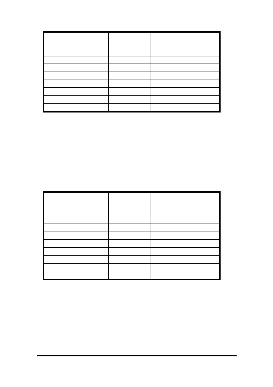
Chart 3. Modem DB25 Connector to Master Port
Async Modem
Serial Port
DB25 Connector
Signal
Direction
232MSS2
Master Port (DTE)
DB25 Connector
2
<-----------
2
3
----------->
3
4
<-----------
6*
5
----------->
20*
7
<--------->
7
8
----------->
5
20
<-----------
4
* Pins are tied together inside the 232MSS2, they are not
connected to ports A, B, C, or D.
NOTE: When connecting a DTE device to ports A, B, C, or D of
the smart switch, refer to Charts 8 and 9.
Chart 4. IBM PC DB25 Connector to Ports A - D (DTE)
Master port configured as a DCE port.
IBM PC
Serial Port
DB25 Connector
Signal
Direction
232MSS2
Ports A - D (DTE)
DB9 Connector
2
----------->
2
3
<-----------
3
4
----------->
8
5
<----------
7
6
<----------
6*
7
<--------->
5
8
<-----------
4*
20
----------->
4*
* Pins are tied together inside the 232MSS2, they are not
connected to the master port.