B&B Electronics ZZ24D-NA(NB,NC,ND)-SR - Quick Start Guide User Manual
Page 4
7516R8_ZlinxIO-0812qsg – Peer-to-Peer Mode
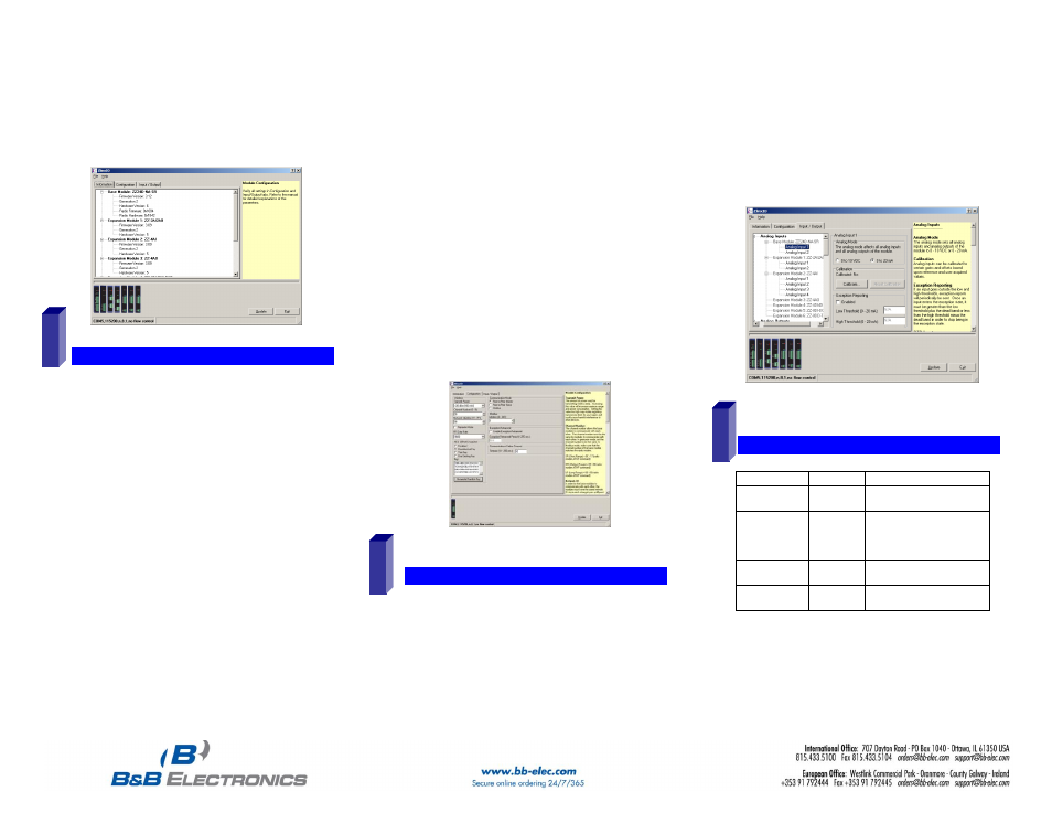
Zlinx Modules on startup. Zlinx I/O will open and display
the Information tab showing model numbers, version
numbers of the attached Base and Expansion Modules.
o
Make sure that all Base Modules have the same
firmware revision*
o
Make sure that all Expansion Modules have the
same firmware version*
*This can be verified under the Information tab.
C
C
o
o
n
n
f
f
i
i
g
g
u
u
r
r
e
e
C
C
o
o
m
m
m
m
u
u
n
n
i
i
c
c
a
a
t
t
i
i
o
o
n
n
M
M
o
o
d
d
e
e
On the Configuration tab:
Select Peer-to-Peer (P2P) Master on one set of Zlinx I/O
Modules and P2P Slave on the other set of Zlinx I/O
Modules.
Configure System 1 (see figure in Section 2) as described
below:
o
Set the P2PMaster address to match the Slave.
o
Set Polling Rate to update at an acceptable rate.
o
Set Retry Count for number of tries before lost
communication indication is required.
o
Configure the Wireless settings:
Select the desired RF Transmit Power (not
applicable for MR models).
Select the desired OTA Data Rate (not applicable
for SR, MR, and LR-868 models).
Set Channel Number to match the device you will
be communicating with.
Set Network Identifier to match device you will be
communicating with.
Select Encryption (not applicable to MR models).
Note: Refer to the manual for more details
concerning wireless settings.
o
Click Update to save configuration.
Configure System 2 (see figure in Section 2) as
described below:
o
Set the P2P Slave address to match the Master.
o
Set Polling Rate to update at an acceptable rate.
o
Set Retry Count for number of tries before lost
communication indication is required.
o
Configure the Wireless settings:
Select the desired RF Transmit Power (not
applicable for MR models).
Select the desired OTA Data Rate (not applicable
for SR, MR, and LR-868 models)
Set Channel Number to match device you will be
communicating with.
Set Network Identifier to match device you will be
communicating with.
Select Encryption (not applicable to MR models)
Note: Refer to the manual for more details
concerning wireless settings.
o
Click Update to save configuration.
C
C
o
o
n
n
f
f
i
i
g
g
u
u
r
r
e
e
I
I
n
n
p
p
u
u
t
t
/
/
O
O
u
u
t
t
p
p
u
u
t
t
Set Analog Inputs and Outputs for 0 to 10 VDC or 0 to 20
mA as required (setting one sets all analog I/O for that
Module).
Set Digital Inputs for Discrete or Counter, as required.
Set Calibration option if you desire to better match a
sensor, or a portion of a signal, to the I/O.
Check Enabled checkbox and set appropriate values for
parameters in Failsafe section to go to the user-defined
values for AO or DO in case of communication failure.
Check Use Output to Indicate Communication Failure
checkbox in Dedicated Comm Fail Alarm section to
configure the first DO on the Base Module to be a
communication failure alarm indicator.
Check Invert Output checkbox to invert the logic of Digital
Outputs on Base or Expansion Modules.
Click Update button to apply the settings.
O
O
p
p
e
e
r
r
a
a
t
t
i
i
o
o
n
n
LED
STATUS
FUNCTION
Power
Red
Solid
Power applied
RSSI
Tricolor
Off
Red
Yellow
Green
No radio signal
Weak radio signal
OK radio signal
Strong radio signal
RF Data
Green
Off
Blinking
No radio link data
Radio link data TD/RD traffic
Bus
Green
Off
Blinking
No local bus data
Local bus data TD/RD traffic
Refer to the Troubleshooting Section of the Manual if operation
is not successful.
7
8
9