Rainbow Electronics DDS1693 User Manual
Page 11
DS1689/DS1693
11 of 32
PERIODIC INTERRUPT RATE AND
SQUARE WAVE OUTPUT FREQUENCY Table 2
EXT. REG. B
SELECT BITS REGISTER A
E32K
RS3
RS2
RS1
RS0
t
PI
PERIODIC
INTERRUPT RATE
SQW OUTPUT
FREQUENCY
0
0
0
0
0
None
None
0
0
0
0
1
3.90625 ms
256 Hz
0
0
0
1
0
7.8125 ms
128 Hz
0
0
0
1
1
122.070
ms
8.192 kHz
0
0
1
0
0
244.141
ms
4.096 kHz
0
0
1
0
1
488.281
ms
2.048 kHz
0
0
1
1
0
976.5625
ms
1.024 kHz
0
0
1
1
1
1.953125 ms
512 Hz
0
1
0
0
0
3.90625 ms
256 Hz
0
1
0
0
1
7.8125 ms
128 Hz
0
1
0
1
0
15.625 ms
64 Hz
0
1
0
1
1
31.25 ms
32 Hz
0
1
1
0
0
62.5 ms
16 Hz
0
1
1
0
1
125 ms
8 Hz
0
1
1
1
0
250 ms
4 Hz
0
1
1
1
1
500 ms
2 Hz
1
X
X
X
X
*
32.768 kHz
*RS3-RS0 determine periodic interrupt rates as listed for E32K=0.
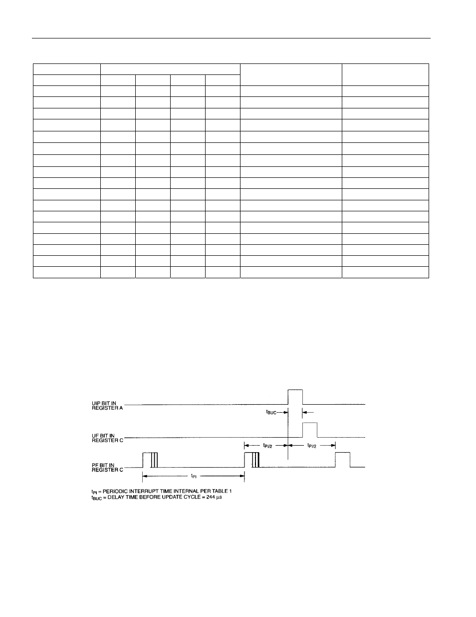
The third method uses a periodic interrupt to determine if an update cycle is in progress. The UIP bit in
Register A is set high between the setting of the PF bit in Register C (see Figure 3). Periodic interrupts
that occur at a rate of greater than t
BUC
allow valid time and date information to be reached at each
occurrence of the periodic interrupt. The reads should be complete within (t
PI
/ 2+t
BUC
) to ensure that data
is not read during the update cycle.
UPDATE-ENDED AND PERIODIC INTERRUPT RELATIONSHIP Figure 3