Electrical characteristics (continued) – Rainbow Electronics MAX3798 User Manual
Page 7
MAX3798
1.0625Gbps to 10.32Gbps, Integrated, Low-
Power SFP+ Limiting Amplifier and VCSEL Driver
_______________________________________________________________________________________
7
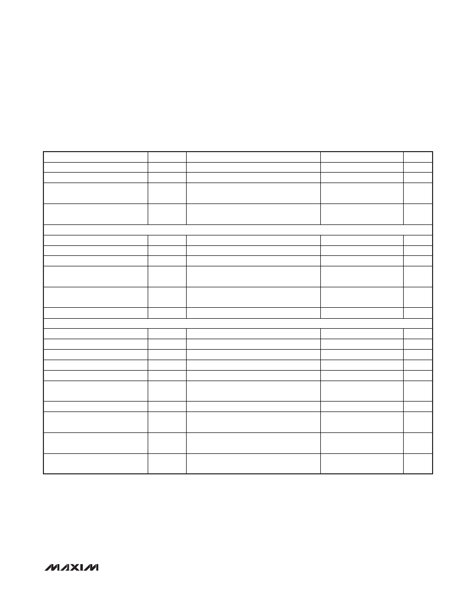
ELECTRICAL CHARACTERISTICS (continued)
(V
CC
= 2.85V to 3.63V, T
A
= -40°C to +85°C, CML receiver output load is AC-coupled to differential 100
Ω, C
AZ
= 1nF, transmitter out-
put load is AC-coupled to differential 100
Ω (see Figure 1), typical values are at +25°C, V
CC
= 3.3V, I
BIAS
= 6mA, I
MOD
= 6mA, unless
otherwise specified. Registers are set to default values unless otherwise noted, and the 3-wire interface is static during measure-
ments. For testing, the MODE_SEL bit was used and the MSEL pin was left open.)
PARAMETER SYMBOL
CONDITIONS
MIN
TYP
MAX
UNITS
DISABLE Input Low Voltage
V
IL
0
0.8 V
DISABLE Input Impedance
R
PULL
Internal pullup resistor
5.5
8
10.5
k
LOS, FAULT Output High Voltage
V
OH
R
LOS
= 4.7k
- 10k to V
CC
,
R
FAULT
= 4.7k
- 10k to V
CC
V
CC
-
0.5
V
CC
V
LOS, FAULT Output Low Voltage
V
OL
R
LOS
= 4.7k
- 10k to V
CC
,
R
FAULT
= 4.7k
- 10k to V
CC
0 0.4
V
3-WIRE DIGITAL I/O SPECIFICATIONS (SDA, CSEL, SCL)
Input High Voltage
V
IH
2.0 V
CC
V
Input Low Voltage
V
IL
0.8 V
Input Hysteresis
V
HYST
0.082
V
Input Leakage Current
I
IL
, I
IH
V
IN
= 0V or V
CC
; internal pullup or pulldown
(75k
typical)
150
μA
Output High Voltage
V
OH
External pullup of 4.7k
to V
CC
V
CC
-
0.5
V
Output Low Voltage
V
OL
External pullup of 4.7k
to V
CC
0.4
V
3-WIRE DIGITAL INTERFACE TIMING CHARACTERISTICS (see Figure 4)
SCL Clock Frequency
f
SCL
400 1000 kHz
SCL Pulse-Width High
t
CH
0.5
μs
SCL Pulse-Width Low
t
CL
0.5
μs
SDA Setup Time
t
DS
100
ns
SDA Hold Time
t
DH
100
ns
SCL Rise to SDA Propagation
Time
t
D
5
ns
CSEL Pulse-Width Low
t
CSW
500
ns
CSEL Leading Time Before the
First SCL Edge
t
L
500
ns
CSEL Trailing Time After the
Last SCL Edge
t
T
500
ns
SDA, SCL External Load
C
B
Total bus capacitance on one line with
4.7k
pullup to V
CC
20
pF
Note 1: Supply current is measured with unterminated receiver CML output or with AC-coupled Rx output termination. The Tx out-
put and the bias current output must be connected to a separate supply in order to remove the modulation/bias current
portion from the supply current. BIAS must be connected to 2.0V. TOUT+/- must be connected through 50
Ω load resistors
to a separate supply voltage.
Note 2: Guaranteed by design and characterization, T
A
= -40°C to +95°C.
Note 3: The data input transition time is controlled by a 4th-order Bessel filter with -3dB frequency = 0.75 x data rate. The determin-
istic jitter caused by this filter is not included in the DJ generation specifications.
Note 4: Test pattern is 00001111 at 4.25Gbps for MODE_SEL = 0. Test pattern is 00001111 at 8.5Gbps for MODE_SEL = 1.