Max3798 – Rainbow Electronics MAX3798 User Manual
Page 22
MAX3798
Register Descriptions
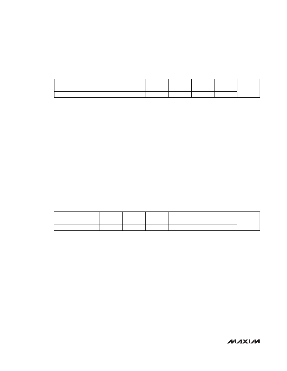
Receiver Control Register 1 (RXCTRL1)
Bit 3: CAZX. When CAZX is set to 0, no external capacitor is required (CAZ1 and CAZ2). When CAZX is set to 1, an
external capacitor with a minimum value of 2nF is required between CAZ1 and CAZ2.
0 = no capacitor
1 = capacitor connected
Bit 2: GMEN. Allows faster switching between data paths.
0 = disabled
1 = enabled
Bit 1: MODE_SEL. MODE_SEL combined with the MSEL pin through a logic-OR function selects between the high-
gain mode (1.0625Gbps to 8.5Gbps) or high-bandwidth mode (1.0625Gbps to 10.32Gbps).
Logic-OR output 0 = high-gain mode
Logic-OR output 1 = high-bandwidth mode
Bit 0: SLEW_RATE. Controls the slew rate of the output stage to reduce the effects of EMI at slower data rates.
Effective when MODE_SEL = 0 and MSEL = GND only.
0 = 50ps
1 = 30ps
Receiver Control Register 2 (RXCTRL2)
Bit 6: LOS_EN. Controls the LOS circuitry. When RX_EN is set to 0 the LOS detector is also disabled.
0 = disabled
1 = enabled
Bit 5: LOS_POL. Controls the output polarity of the LOS pin.
0 = inverse
1 = normal
Bit 4: RX_POL. Controls the polarity of the receiver signal path.
0 = inverse
1 = normal
Bit 3: SQ_EN: When SQ_EN = 1, the LOS controls the output circuitry.
0 = disabled
1 = enabled
1.0625Gbps to 10.32Gbps, Integrated, Low-
Power SFP+ Limiting Amplifier and VCSEL Driver
22
______________________________________________________________________________________
Bit #
7 6 5 4 3 2 1 0
ADDRESS
Name
X X X X
CAZX
GMEN
MODE_SEL
SLEW_RATE
Default
Value
X X X X 1 1 0 0
H0x00
Bit #
7 6 5 4 3 2 1 0
ADDRESS
Name X
LOS_EN
LOS_POL
RX_POL
SQ_EN
RX_EN
RXDE_EN
AZ_EN
Default
Value
X 1 1 1 0 1 0 1
H0x01