Table 3. s sk kiip p pwm table, Pwm controller – Rainbow Electronics MAX1636 User Manual
Page 12
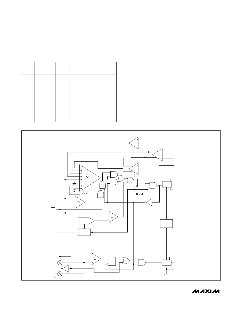
PWM Controller
The heart of the current-mode PWM controller is a
multi-input, open-loop comparator that sums four sig-
nals: the output voltage error signal with respect to the
reference voltage, the current-sense signal, the inte-
grated voltage-feedback signal, and the slope-
compensation ramp (Figure 3).
The PWM controller is a direct-summing type, lacking a
traditional error amplifier and the phase shift associat-
ed with it. This direct-summing configuration approach-
es ideal cycle-by-cycle control over the output voltage
(Figure 4).
When SKIP = low, Idle Mode circuitry automatically
optimizes efficiency throughout the load-current range.
Idle Mode dramatically improves light-load efficiency
MAX1636
Low-Voltage, Precision Step-Down
Controller for Portable CPU Power
12
______________________________________________________________________________________
Low
Light
Idle
LOAD
CURRENT
Pulse-skipping,
discontinuous inductor
current
MODE
DESCRIPTION
PWM
High
Light
PWM
Constant-frequency PWM,
continuous inductor current
PWM
High
Heavy
Constant-frequency PWM,
continuous inductor current
Low
Heavy
Constant-frequency PWM,
continuous inductor current
S
SK
KIIP
P
Table 3. S
SK
KIIP
P PWM Table
SHOOT-
THROUGH
CONTROL
R
Q
30mV
R
Q
LEVEL
SHIFT
1X
gm
2X
OSC
LEVEL
SHIFT
CURRENT
LIMIT
SYNCHRONOUS
RECTIFIER CONTROL
SHDN
CK
-100mV
CSH
CSL
CC
REF
FB
BST
DH
LX
VGG
DL
PGND
S
S
SLOPE
COMPENSATION
SKIP
COUNTER
DAC
SOFT-START
Figure 3. PWM Controller Functional Diagram