Pin description (continued) – Rainbow Electronics MAX132 User Manual
Page 5
MAX132
±18-Bit ADC with Serial Interface
_______________________________________________________________________________________
5
MAX132
CREF-
CREF+
1
20
CS
602k
4
SCLK
3
DOUT
2
DIN
11
EOC
7
P0
8
P1
9
P2
10
P3
23
19
22
21
-5V
512mV INPUT
18
17
6
5
15pF
15pF
BUF OUT
INT OUT
INT IN
4.7nF
32,768Hz
REF+
REF-
16
15
AGND
IN LO
14
IN HI
13
12
V-
24
V+
DGND
OSC2
OSC1
0.1
µ
F
120k
100k
40.2k
2.5V
MAX872
+5V
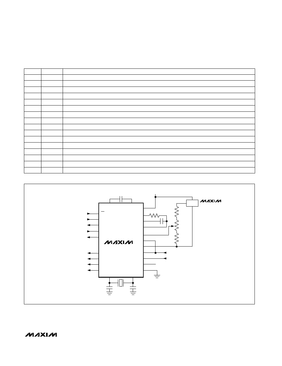
Figure 1. Test and Typical Application Circuit
_________________________________________________Pin Description (continued)
End of Conversion Output goes high at end of conversion.
EOC
11
Positive Supply, nominally +5V
V+
24
User-programmable output bit 3—programmed through the serial port.
P3
10
Negative Reference Capacitor connection
CREF-
20
Positive Reference Capacitor connection
CREF+
19
Positive Reference Input
REF+
18
Negative Reference Input
REF-
17
Analog Ground
AGND
16
Negative Analog Input
IN LO
15
Buffer-Amplifier Output drives the integrator resistor.
BUF OUT
23
User-programmable output bit 2—programmed through the serial port.
P2
9
PIN
Integrator Output. To minimize noise, this pin should drive the capacitor’s outside foil (negative end).
INT OUT
22
Integrator Input. Connect the integration capacitor between INT IN and INT OUT.
INT IN
21
FUNCTION
NAME
Positive Analog Input
IN HI
14
Negative Supply, nominally -5V
V-
13
Digital Ground—power-supply return
DGND
12