Typical operating characteristics, Pin description – Rainbow Electronics MAX132 User Manual
Page 4
MAX132
±18-Bit ADC with Serial Interface
4
_______________________________________________________________________________________
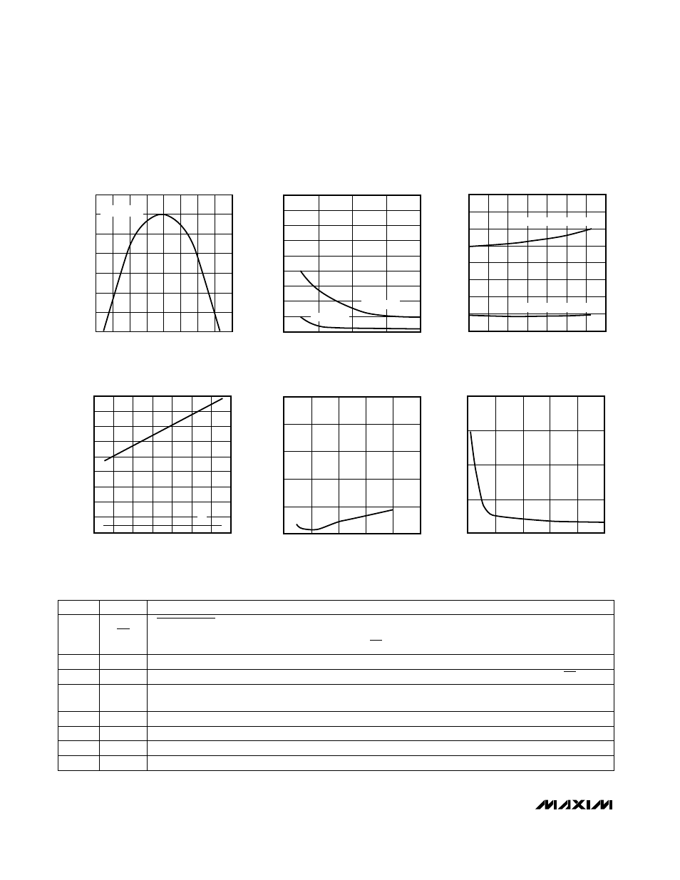
__________________________________________Typical Operating Characteristics
-0.30
-0.25
-0.20
-0.15
-0.10
-0.05
0.05
0
ERROR vs. COMMON-MODE
INPUT VOLTAGE (V
IN
LO–AGND)
MAX132-01
COMMON-MODE VOLTAGE (V)
-3
-2
-1
0
1
2
3
4
-4
ERROR (% OF FSR)
IN HI = IN LO
0
0
0.5
1.5
50Hz/60Hz READ-ZERO OFFSET
vs. VREF
1.5
3.5
MAX132-02
VREF (V)
READ-ZERO OFFSET (% OF FSR)
1.0
2.0
2.5
4.0
1.0
0.5
3.0
2.0
4.5
60Hz MODE
50Hz MODE
0
-40
-20
20
50Hz/60Hz READ-ZERO OFFSET
vs. TEMPERATURE
0.6
1.4
MAX132-03
TEMPERATURE (°C)
0
40
60
80
100
1.0
1.6
0.4
0.2
1.2
0.8
READ-ZERO OFFSET (% OF FSR)
60Hz MODE, VREF = 545mV
50Hz MODE, VREF = 655mV
-40
0
50
150
SUPPLY CURRENT
vs. CRYSTAL FREQUENCY
20
100
MAX132-04
CRYSTAL FREQUENCY (kHz)
SUPPLY CURRENT (
µ
A)
100
200
250
300
350
60
120
0
-20
80
40
140
V-
V+
0.10
0.08
0.06
0.04
0.02
0
FULL-SCALE ROLLOVER ERROR
vs. VREF
MAX132-05
VREF (V)
0
0.5
1.0
1.5
2.5
2.0
ROLLOVER ERROR (% OF FSA)
0
5
10
15
20
NOISE vs. NUMBER
OF SAMPLES AVERAGED
MAX132-06
NUMBER OF SAMPLES AVERAGED
0
10
20
30
50
40
NOISE (
µ
V
RMS
)
______________________________________________________________Pin Description
Oscillator Output 2 is normally connected to a 32,768Hz crystal. Do not connect with external clock source.
OSC2
5
Serial Clock Input. On SCLK’s rising edge, data is shifted into the internal shift register through DIN. On
SCLK’s falling edge, data is clocked out of DOUT.
SCLK
4
Serial Data Out, D7 first bit out. Data is clocked out at the falling edge of SCLK. High impedance when CSis high.
DOUT
3
User-programmable output bit 1—programmed through the serial port.
P1
8
User-programmable output bit 0—programmed through the serial port.
P0
7
Oscillator Input 1 is normally connected to a 32,768Hz crystal, or may be connected to an external clock.
OSC1
6
Serial Data In, D7 first bit in. Data is clocked into the register on the rising edge of SCLK.
DIN
2
PIN
CHIP SELECT Input has 3 functions: 1) When low, selects IC for communication; 2) on rising edge, loads
input shift register data into one of the command registers; 3) on falling edge, loads data from one of the
output registers into the output shift register. When CS is high, DOUT is high impedance.
CS
1
FUNCTION
NAME