Interfacing to a µp parallel port – Rainbow Electronics MAX132 User Manual
Page 15
MAX132
±18-Bit ADC with Serial Interface
______________________________________________________________________________________
15
MAX132
RW2
RW1
V-
V+
DGND
IN
GND
AGND
RW1, RW2 WIRE RESISTANCE
4.096V
1
13
CS
V
S
250
Ω
0.1%
2k
600k
0.1
µ
F
10
µ
F
2
DIN
3
DOUT
4
SCLK
11
EOC
7
PG0
8
PG1
V
R
9
PG2
10
PG3
14
IN HI
15
23
24
-5V
+5V
22
21
19
20
18
17
5
6
12
16
IN LO
BUF OUT
INT OUT
OUT
INT IN
4.7nF
32,768Hz
CREF+
CHIP SELECT
DATA IN
DATA OUT
SERIAL-
DATA
INTERFACE
CLOCK
RTD
PT100
CREF-
REF+ IN
REF- IN
OSC2
OSC1
IC2
MAX872
IC1
0.1
µ
F
0.1
µ
F
10
µ
F
+5V
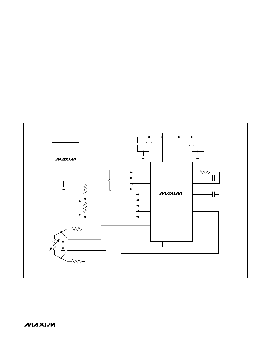
Figure 11. Ratiometric Configuration Using the Differential Reference Inputs
SPI is a trademark of Motorola, Inc. Microwire is a trademark of National Semiconductor Corp.
of the overall accuracy of the current source. The cur-
rent source delivers 2mA, resulting in about 500mV
across the 250
Ω
resistor—suitable to fit the MAX132’s
±512mV full-scale range. Note that the accuracy of the
reference resistor (0.1%) sets the circuit’s accuracy.
The power consumption of the RTD sensor is small
(0.5mW), minimizing errors caused by self-heating.
Interfacing to a µP Parallel Port
Figure 12 shows a high-level software subroutine for
reading output/status data and writing command data
to the MAX132. It provides an algorithm for serial com-
munication when the µP port does not have a prede-
fined serial interface protocol (i.e., SPI™ or Microwire™).
The routine sends command data (TxByte) to the
MAX132 while concurrently collecting the MAX132’s
output register data (selected by the
previous
write
cycle). Note that a write is required before each read to
change the next output register to be read, and that
the subroutine must be repeated three times to read
the output status register, Output Register 0, and
Output Register 1.