Electrical characteristics (continued) – Rainbow Electronics MAX1421 User Manual
Page 4
MAX1421
12-Bit, 40Msps, +3.3V, Low-Power ADC
with Internal Reference
4
_______________________________________________________________________________________
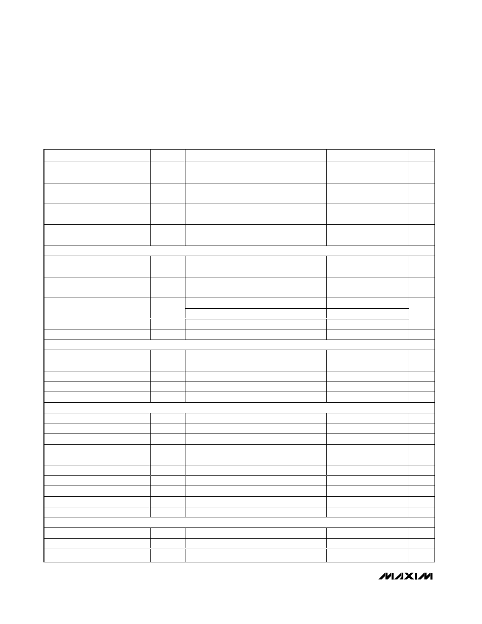
ELECTRICAL CHARACTERISTICS (continued)
(V
AVDD
= V
DVDD
= +3.3V, AGND = DGND = 0, V
IN
= ±1.024V, differential input voltage at -0.5dB FS, internal reference,
f
CLK
= 40MHz (50% duty cycle), digital output load C
L
≈ 10pF, T
A
= T
MIN
to T
MAX
, unless otherwise noted. Typical values are at
T
A
= +25°C.)
PARAMETER
SYMBOL
CONDITIONS
MIN
TYP
MAX
UNITS
Differential Reference Voltage
Range
V
DIFF
V
DIFF
= V
REFP
- V
REFN
1.024
±10%
V
CML Input Voltage Range
V
CML
1.65
±10%
V
REFP Input Voltage Range
V
REFP
V
CML
+
V
DIFF
/2
V
REFN Input Voltage Range
V
REFN
V
CML
-
V
DIFF
/2
V
DIGITAL INPUTS (CLK,
CLK, OE, PD)
Input Logic High
V
IH
0.7
✕
V
DVDD
V
Input Logic Low
V
IL
0.3
✕
V
DVDD
V
CLK,
CLK
±330
PD
-20
20
Input Current
OE
-20
20
µA
Input Capacitance
10
pF
DIGITAL OUTPUTS (D0–D11)
Output Logic High
V
OH
I
OH
= 200µA
V
DVDD
- 0.5
V
DVDD
V
Output Logic Low
V
OL
I
OL
= -200µA
0
0.5
V
Three-State Leakage
-10
10
µA
Three-State Capacitance
2
pF
POWER REQUIREMENTS
Analog Supply Voltage
V
AVDD
3.135
3.3
3.465
V
Digital Supply Voltage
V
DVDD
2.7
3.3
3.6
V
Analog Supply Current
I
AVDD
52
65
mA
Analog Supply Current with
Internal Reference in Shutdown
REFIN = AGND
50
63
mA
Analog Shutdown Current
PD = DV
DD
20
µA
Digital Supply Current
I
DVDD
5.5
mA
Digital Shutdown Current
PD = DV
DD
20
µA
Power Dissipation
P
DISS
Analog power
188
214
mW
Power-Supply Rejection Ratio
PSRR
(Note 9)
±1
mV/V
TIMING CHARACTERISTICS
Clock Frequency
f
CLK
Figure 5
0.1
40
MHz
Clock High
t
CH
Figure 5, clock period 25ns
12.5
ns
Clock Low
t
CL
Figure 5, clock period 25ns
12.5
ns